Actuation assembly with a track and follower for use in moving a wing tip device on an aircraft wing

a technology of actuation assembly and track, which is applied in the direction of wing adjustment, drag reduction, etc., can solve the problem that the follower is substantially inability to react to the load into the sliding chassis, and achieve the effect of reducing vibration

Active Publication Date: 2019-11-05
AIRBUS OPERATIONS LTD
View PDF17 Cites 3 Cited by
  • Summary
  • Abstract
  • Description
  • Claims
  • Application Information

AI Technical Summary

Benefits of technology

[0010]According to a first aspect of the invention, there is provided an aircraft wing comprising a fixed wing and a wing tip device at the tip thereof, wherein the wing tip device is configurable between: (i) a flight configuration for use during flight and (ii) a ground configuration for use during ground-based operations, in which ground configuration the wing tip device is moved away from the flight configuration such that the span of the aircraft wing is reduced, wherein in the flight configuration, the wing tip device and the fixed wing engage via a load transfer arrangement, such that flight loads may be transferred from the wing tip device into the fixed wing, but during movement of the wing tip device away from the flight configuration and towards the ground configuration, the load transfer arrangement between the wing and wing tip device is disengaged, wherein the wing comprises an actuation assembly for moving the wing tip device between the flight and the ground configuration, the actuation assembly comprising a sliding chassis coupled to the wing tip device, the sliding chassis being slideably moveable relative to the fixed wing via a track and follower arrangement. The track comprises a first portion of a first width and a second portion of a second width, narrower than the first width, arranged such that when the load transfer arrangement between the wing and wing tip device is disengaged, the follower is located in the second portion of the track in a tight fit, such that the follower is unable to move within the width of that second portion, but when the wing tip device is in the flight configuration and the load transfer arrangement is engaged, the follower is located in the first portion of the track and is able to move within the width of that first portion, thereby substantially isolating the sliding chassis from flight loads.
[0011]Since the follower is located in the relatively wide track when the wing tip device is in the flight configuration, the follower is substantially unable to react loads into the sliding chassis (because it would simply move within the width of the track under any such loading). Instead, the loads are transferred via the load transfer arrangement. This means that the actuation assembly does not need to be sized to cope with the flight loads, enabling the actuation assembly to be relatively small and / or lightweight. Furthermore, by providing a relatively narrow track into which the follower can be located in a tight fit (when the load transfer arrangement between the wing and wing tip device is disengaged—for example during movement to the ground configuration) the actuation assembly can still be arranged to transfer the (typically smaller) loads occurring in, or during movement to, the ground configuration.
[0013]In principle, the follower may be any arrangement that is able to perform the function of following the track. The follower may be a bogie, moveable along the track. The bogie may comprise two wheels. The wheels may be mounted on a bogie body. Using a bogie has been found to be especially beneficial as it provides a relatively low-wear arrangement.
[0014]The bogie may be biased into an expanded orientation such that it touches both sides of the track. The expanded orientation may be such that when the bogie is located in the first portion of the track, the bogie still touches both sides of the track. Biasing the bogie in this manner has been found to reduce vibration and / or cater for tolerances, since it ensures there is a contact on both sides of the track by the bogie.
[0019]The actuation assembly may be arranged to move the wing tip device from the flight configuration to the ground configuration in a two-stage movement, the two-stage movement comprising a first stage in which the wing tip device is translated away from the flight configuration in a linear movement only, and a second, subsequent stage, in which the wing tip device is rotated to the ground configuration. A two stage movement, particularly a two stage movement in which the first stage is a linear movement only, has been found to be particularly beneficial. For example, having a first stage that is only a linear movement, tends to reduce the wear on any sealing arrangement between the fixed wing and the wing tip device, because it tends to avoid relatively rotation occurring between sealing surfaces. Alternatively or additionally, having a first stage that is only a linear movement, may facilitate engagement between the fixed wing and the wing tip device to ensure an effective load-transfer arrangement.
[0022]One of the fixed wing and the wing tip device may comprise a plurality of male members, such as spigots. The other of the fixed wing and the wing tip device may comprise a plurality of corresponding female members, such as bushes. The load transfer arrangement may comprise the male and female members. The female members may be arranged to receive the male members when the wing tip device is in the flight configuration, such that flight loads may be transferred, via the male members, from the wing tip device into the fixed wing. Such an arrangement tends to be beneficial because it enables flight loads to be adequately managed and reacted into the fixed wing. When the load transfer arrangement is disengaged the male members may be separated from the female members.

Problems solved by technology

Since the follower is located in the relatively wide track when the wing tip device is in the flight configuration, the follower is substantially unable to react loads into the sliding chassis (because it would simply move within the width of the track under any such loading).

Method used


Image

  • Actuation assembly with a track and follower for use in moving a wing tip device on an aircraft wing
  • Actuation assembly with a track and follower for use in moving a wing tip device on an aircraft wing
  • Actuation assembly with a track and follower for use in moving a wing tip device on an aircraft wing

Examples


Embodiment Construction

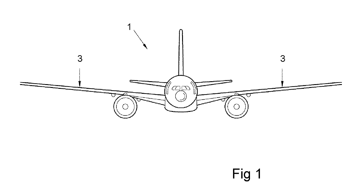
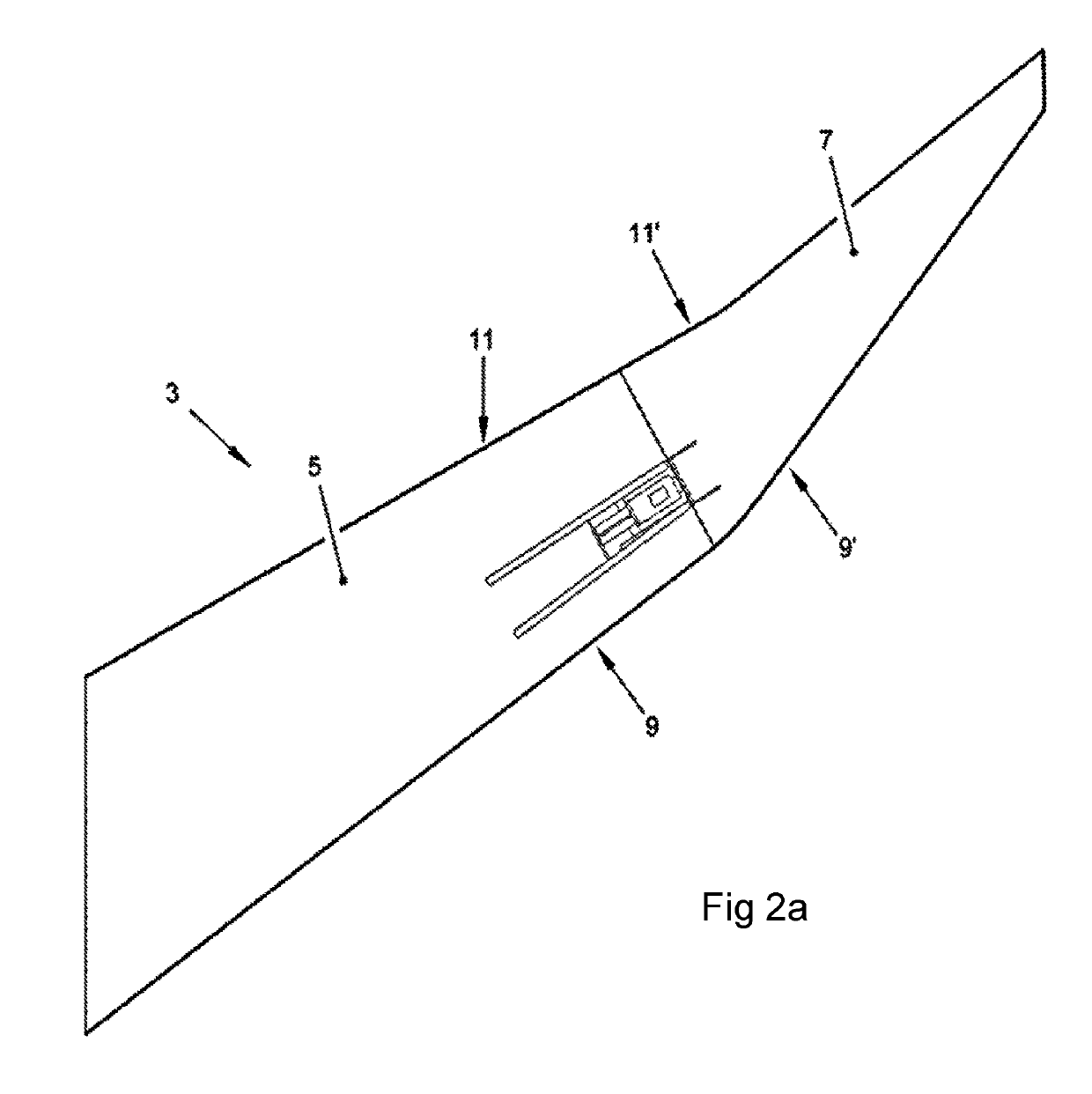
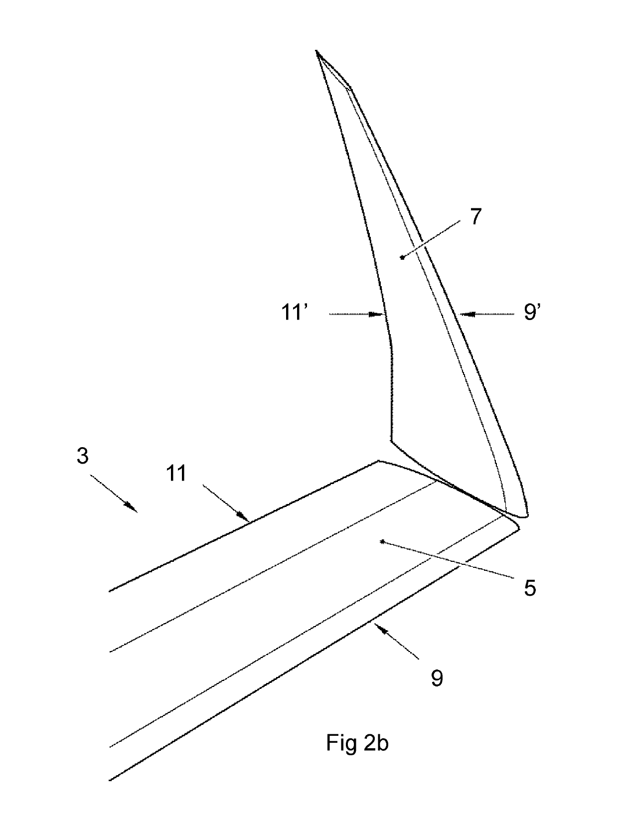
[0064]FIG. 1 is a schematic drawing showing an aircraft 1 having aircraft wings 3 according to a first embodiment of the invention. The end of one of the wings 3 on the aircraft 1 is shown in more detail in FIGS. 2a and 2b, to which reference is now made:

[0065]The wing 3 comprises a fixed wing 5 extending from the wing root at the aircraft fuselage, to a tip. At the tip of the fixed wing 5 there is a wing tip device 7. The wing tip device 7 is moveable between a flight configuration (shown in FIG. 2a) and a ground configuration (shown in FIG. 2b).

[0066]In the flight configuration the wing tip device 7 is effectively an extension of the fixed wing 5, such that the leading and trailing edges 9′, 11′ of the wing tip device are continuations of the leading and trailing edges 9, 11 of the fixed wing 5, and the upper and lower surfaces of the wing tip device 7 are continuations of the upper and lower surfaces of the fixed wing 5. The fixed wing and the wing tip device together form a main...


PUM


Abstract

An aircraft wing having a wing tip device at the tip thereof is disclosed. The wing tip device is configurable between: a flight configuration for use during flight and a ground configuration for use during ground-based operations to reduce span. In the flight configuration, flight loads may be transferred via a load transfer arrangement from the wing tip device into the fixed wing, but during movement of the wing tip device towards the ground configuration, the load transfer arrangement is disengaged. The wing includes an actuation assembly having a sliding chassis coupled to the wing tip device, via a track and follower arrangement. The track includes a wide portion and a narrow portion.

Description

RELATED APPLICATIONS[0001]The present application claims priority to Great Britain Patent Application Number 1520289.8, filed Nov. 18, 2015, the disclosure of which is hereby incorporated by reference herein in its entirety.BACKGROUND OF THE INVENTION[0002]The present invention relates to aircraft wings and wing tip devices, and more specifically, but not exclusively, to aircraft wings with moveable wing tip devices, actuation assemblies for use in such wings, aircraft incorporating such wings, and to methods of moving a wing tip device.[0003]There is a trend towards increasingly large passenger aircraft, for which it is desirable to have correspondingly large wing spans. However, the maximum aircraft span is effectively limited by airport operating rules which govern various clearances required when manoeuvring around the airport (such as the span and / or ground clearance required for gate entry and safe taxiway usage).[0004]Moveable wing tip devices have been suggested for use on p...

Claims


Application Information

Patent Timeline
Patent Type & Authority Patents(United States)
IPC IPC(8): B64C3/56
CPCB64C3/56Y02T50/14Y02T50/10
Inventor HARDING, MATTHEWNAPIER, STEFANMARONGIU, NICOLA
Owner AIRBUS OPERATIONS LTD
Why Eureka
Try Eureka