Moveable wing tip device, an outer end of a wing, and interfacetherebetween

a technology of wing tip and wing body, which is applied in the direction of airflow influencers, heat reducing structures, spars/stringers, etc., can solve the problems of affecting the maximum aircraft span, affecting and affecting the sealing of the interface between the fixed wing and so as to facilitate the integration of the wing tip device

Active Publication Date: 2019-09-19
AIRBUS OPERATIONS LTD
View PDF0 Cites 1 Cited by
  • Summary
  • Abstract
  • Description
  • Claims
  • Application Information

AI Technical Summary

Benefits of technology

[0033]The wing may comprise a seal support structure located along the second length. The second seal support structure may be orientated parallel to the plane containing the second cut line (for example along the thickness of the wing skin and co-planar with the plane within which the second length extends. This may be beneficial because it can support the seal undergoing pure compression (i.e. compression in a direction perpendicular to the plane containing the second line).
[0034]In principle, the cut forming the second length may be orientated in a number of different directions (so long as the plane it lies in (or is parallel to) also contains the axis of rotation). In some embodiments, the cut forming the second length is orientated in the line-of-flight direction. Such an arrangement tends to be preferable from the aerodynamic point of view. In some other embodiments, the fixed wing comprises a front spar and the cut forming the second length is orientated perpendicular to the front spar. Such an arrangement tends to facilitate integration of the wing tip device with a fixed wing having a leading edge slat in the region of the tip.

Problems solved by technology

However, the maximum aircraft span is effectively limited by airport operating rules which govern various clearances required when manoeuvring around the airport (such as the span and / or ground clearance required for gate entry and safe taxiway usage).
In the arrangement of WO2015 / 150835, sealing the interface between the fixed wing and the wing tip device (when the wing tip device is in the flight configuration) has been found to be problematic.
Whilst a sliding seal may, in principle, be employed, such a solution is sub-optimal because sliding seals tend to be subjected to relatively large amounts of wear.
This may make them susceptible to wear and / or damage and may therefore necessitate frequent inspection and / or replacement of the seal.

Method used


Image

  • Moveable wing tip device, an outer end of a wing, and interfacetherebetween
  • Moveable wing tip device, an outer end of a wing, and interfacetherebetween
  • Moveable wing tip device, an outer end of a wing, and interfacetherebetween

Examples


Embodiment Construction

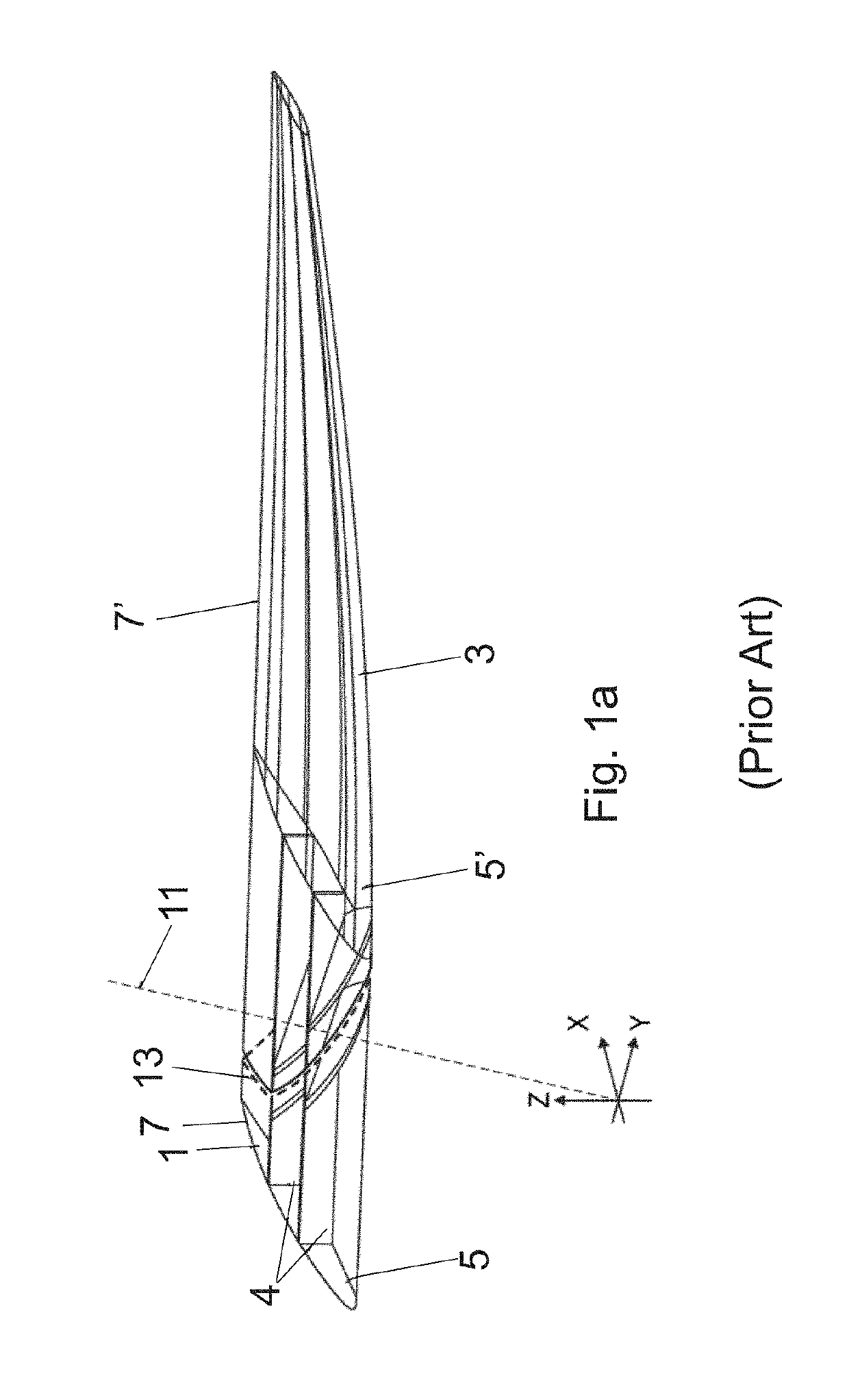
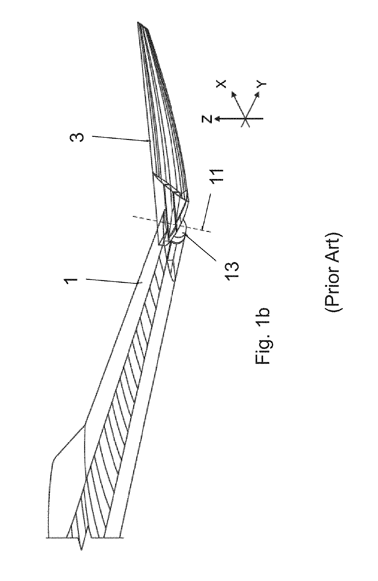
[0076]FIG. 1a is a perspective view of a fixed wing 1 and a wing tip device 3 on an aircraft shown in WO2015 / 150835. In summary, the wing tip device 3 is movable between a flight configuration (FIG. 1a) and a ground configuration (FIG. 1b). In the flight configuration, the leading and trailing edges 5′, 7′ of the wing tip device 3 are continuations of the leading and trailing edges 5, 7 of the fixed wing 1. Furthermore, the upper and lower surfaces of the wing tip device 3 are continuations of the upper and lower surfaces of the fixed wing 1.

[0077]The wing tip device 3 is placed in the flight configuration for flight. In the flight configuration, the wing tip device 3 thus increases the span of the aircraft (thereby providing beneficial aerodynamic effects, for example, reducing the component of induced drag and increasing the lift). In principle, it would be desirable to maintain this large span at all times and simply have a large fixed wing. However, the maximum aircraft span is ...


PUM


Abstract

An aircraft having a wing, including a fixed wing with a wing tip device movably mounted at the outer end thereof is disclosed. The wing tip device is movable between: a flight configuration; and a ground configuration. The wing tip device and the fixed wing are separated along an oblique primary cut plane. The wing tip device and the fixed wing meet along an interfacing cut line. The wing tip device and fixed wing comprise a wing skin with a thickness, and end faces extending across the thickness of the wing skin provide interfacing surfaces corresponding to the interfacing cut line, wherein the interfacing surfaces are angled at a first orientation towards the front of the wing and a second, opposite, orientation towards the rear of the wing.

Description

BACKGROUND OF THE INVENTION[0001]There is a trend towards increasingly large passenger aircraft, for which it is desirable to have correspondingly large wing spans. However, the maximum aircraft span is effectively limited by airport operating rules which govern various clearances required when manoeuvring around the airport (such as the span and / or ground clearance required for gate entry and safe taxiway usage).[0002]To address this problem, various arrangements comprising movable wing tip devices, that specifically enable the span to be reduced in a ground configuration, have been suggested.[0003]WO2015 / 150835 is an example of a suggested arrangement. In the arrangement of WO2015 / 150835 the wing tip device and the fixed wing are separated along an oblique cut plane and the wing tip device is rotatable about an axis of rotation perpendicular to that cut plane.[0004]In the arrangement of WO2015 / 150835, sealing the interface between the fixed wing and the wing tip device (when the w...

Claims


Application Information

Patent Timeline
Patent Type & Authority Applications(United States)
IPC IPC(8): B64C3/56B64C3/26B64C3/18
CPCB64C3/26B64C3/56B64C3/185B64C3/36B64F5/00B64C23/072
Inventor BISHOP, BENJAMIN
Owner AIRBUS OPERATIONS LTD
Why Eureka
Try Eureka