
Sole structure for shoes and shoe with the sole structure

a technology of sole structure and shoe, which is applied in the field of sole structure for shoes and shoes with sole structure, can solve the problems of insufficient cushioning of shock in the sole structure, insufficient cushioning of the midsole, and the shoe touching the ground at the rear of the heel on the lateral side cannot be sufficiently cushioned, so as to achieve the effect of supporting the entire heel region

Active Publication Date: 2019-11-12
MIZUNO CORPORATION
View PDF17 Cites 6 Cited by
  • Summary
  • Abstract
  • Description
  • Claims
  • Application Information

AI Technical Summary

Benefits of technology

[0008]The present disclosure was made in view of these problems, and it is therefore an object of the present disclosure to allow the wearer of shoes who is walking or running to shift his or her body weight on a foot along an optimum load path while supporting the entire heel stably.
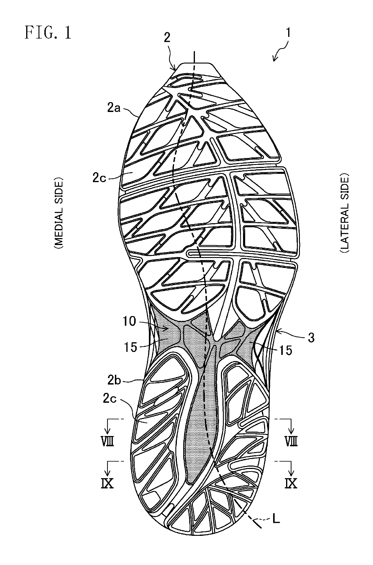
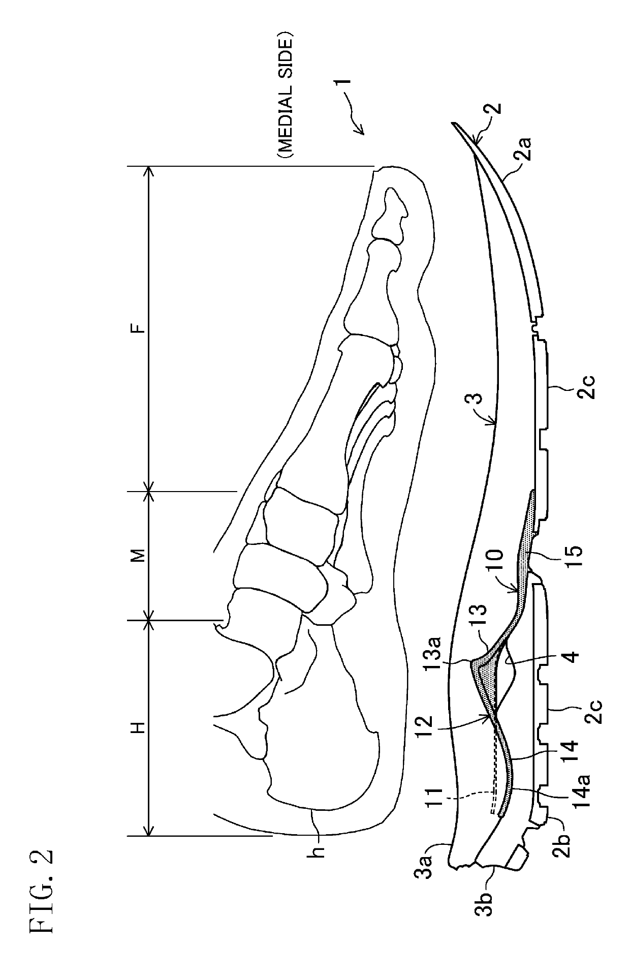
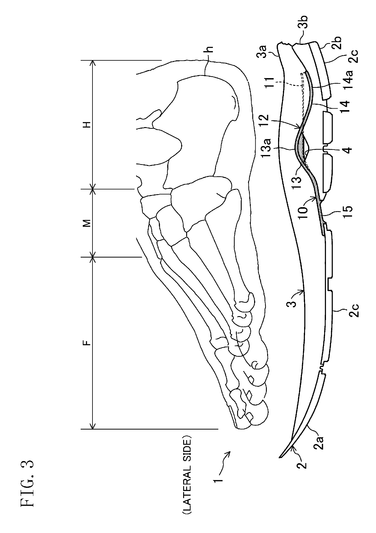
[0010]In the first aspect, at the rear of the heel region, there is a difference in the thickness of the midsole on the top of the supporter in the region extending from the groove of the medial side to the groove of the lateral side. This difference increases the cushioning, which is provided by the midsole on the supporter, more effectively on the medial and lateral sides than in the central portion in the foot width direction. This particularly cushions the initial shock caused when a shoe touches the ground at the rear of the heel region on the lateral side. In the central region of the heel region in the foot width direction, the base of the supporter does not curve like the corrugated sides. This structure of the base easily distributes the shock throughout the base when the shoe touches the ground, thereby cushioning the shock on the central region of the heel region in the foot width direction more effectively than in a case where the shock is cushioned by the midsole only. In addition, the raised and grooves of the corrugated sides of the supporter are stiff enough to prevent the sole structure from being deformed largely at the heel region, and prevent the foot (particularly the ankle) from falling excessively toward the medial or lateral side, even when vertical shock is caused onto the sole support surface of the midsole. This stabilizes the heel region to allow the wearer who is walking or running to shift his or her body weight along an optimum load path. In this manner, the sole structure allows the wearer who is walking or running to shift the body weight on the foot along the optimum load path, while supporting the heel region stably via the supporter.
[0016]In this fourth aspect, the ridges on the medial side further increase the stiffness of the corrugated side on the medial side. This prevents the foot from falling excessively toward the medial side, thereby stabilizing the heel region to allow the wearer who is walking or running to shift his or her body weight along an optimum load path, for example.
[0018]In this fifth aspect, the stiffness of the corrugated side is further increased on the lateral side of the heel region to allow the wearer to smoothly shift his or her body weight at side-step movements on the lateral side of the heel region, when he or she is playing sports such as baseball, football, volleyball, and basketball.
[0020]In this sixth aspect, since the apex of each ridge is located within the region extending from the front of the heel region to the longitudinal center, the stiffness of the corrugated side is increased particularly from the front of the heel region to the longitudinal center.
[0023]As can be seen from the foregoing, the present disclosure allows the wearer who is walking or running to shift his or her body weight on a foot along an optimum load path, while supporting the entire heel region stably via a supporter.

Problems solved by technology

Thus, for example, at the rear of the heel, although the corrugated sheet has increased stiffness, the midsole increases its cushioning insufficiently.
In particular, initial shock when the shoe touches the ground at the rear of the heel on the lateral side cannot be cushioned sufficiently.
This leads to insufficient cushioning of the shock in the sole structure.
In short, the sole structure of Japanese Unexamined Patent Publication No. 11-332606 is not configured to allow the wearer of shoes who is walking or running to shift his or her body weight on a foot along an optimum load path.

Method used


Image

  • Sole structure for shoes and shoe with the sole structure
  • Sole structure for shoes and shoe with the sole structure
  • Sole structure for shoes and shoe with the sole structure

Examples


first embodiment

[0035]FIGS. 1-3 illustrate an overall sole structure 1 for shoes according to a first embodiment of the present disclosure. A pair of shoes including an upper structure (not shown) on this sole structure 1 may be used, for example, as athletic shoes for running and various sports, sneakers for daily use, or rehabilitation shoes. FIGS. 1-3 show the sole structure 1 for a left shoe only. A sole structure 1 for a right shoe is symmetrical to the sole structure 1 for the left shoe. In the following description including the embodiments and variations, only the sole structure 1 for the left shoe will be described and, the description of the sole structure 1 for the right shoe will be omitted. In the following description, the expressions “above,”“upward,”“on a / the top of,”“below,”“downward,” and “under” represent the vertical positional relationship between respective parts of the sole structure 1, and “front” and “rear” represent the longitudinal positional relationship in the sole stru...

second embodiment

[0055]FIG. 10 illustrates a sole structure 1 according to a second embodiment of the present disclosure. In this embodiment, the shape of the corrugated side 12 on the medial side is different from that in the first embodiment. In the other respects, the configurations of the sole structure 1 in this embodiment are the same or similar to those in the first embodiment. In the following description, the same reference characters as those shown in FIGS. 1-9 are used to represent equivalent elements, and the explanation thereof will be omitted.

[0056]As shown in FIG. 10, in this embodiment, a plurality of (e.g., two in the figure) ridges 13 and 13 are provided so as to be arranged longitudinally continuously with each other on the medial side of the heel region H. A recessed intermediate portion 16, which curves like the groove 14, is smoothly continuous between the ridges 13 and 13. The groove 14 is provided continuously with the rear of the ridge 13 located at the end. The recessed int...


PUM

PropertyMeasurementUnit
elasticaaaaaaaaaa
thicknessaaaaaaaaaa
widthaaaaaaaaaa

Abstract

A sole structure includes an outsole having a ground surface as a lower surface; a midsole stacked on a top of the outsole and made of an elastic material; and a supporter provided around a middle of the midsole in a thickness direction, and extending longitudinally to include a heel region corresponding to a heel of a foot. The supporter includes a base provided in a central region of the heel region in a foot width direction, and a corrugated side provided continuously with each side of the base in the foot width direction, and including a ridge with its apex located above the base, and a groove provided continuously with a rear of the ridge with its bottom located below the base at the rear of the heel region.

Description

CROSS-REFERENCE TO RELATED APPLICATION[0001]This application claims priority to Japanese Patent Application No. 2016-095384 filed on May 11, 2016, the entire disclosure of which is hereby incorporated by reference.BACKGROUND OF THE INVENTION[0002]The present disclosure relates to a sole structure for shoes and a shoe with the sole structure.[0003]A sole structure for athletic shoes has been generally widely known, which includes, as major components, a midsole made of a soft elastic material and an outsole bonded to the lower surface of the midsole, and focuses on cushioning. As an improvement of this sole structure, for example, Japanese Unexamined Patent Publication No. 11-332606, suggests a sole structure for athletic shoes that reduces excessive deformation of the shoes in a foot width direction (i.e., transverse deformation) when the shoes are touching the ground.[0004]The sole structure disclosed in this Japanese Unexamined Patent Publication No. 11-332606 includes a midsole, ...

Claims


Application Information

Patent Timeline
Patent Type & Authority Patents(United States)
IPC IPC(8): A43B13/12A43B13/04A43B13/18A43B13/14
CPCA43B13/186A43B13/188A43B13/04A43B13/141A43B13/127A43B13/185
Inventor IUCHI, KAZUNORITAKESHITA, TAKESHIMATSUI, SHOGO
Owner MIZUNO CORPORATION
Learn More