
Detecting apparatus and volatile organic compound detector

a technology of volatile organic compounds and detecting equipment, which is applied in the direction of measurement apparatus bearings/suspensions, instruments, human health protection, etc., can solve the problems of inaccurate follow-up detection process of conventional voc detectors and inability to use conventional detecting equipment to detect volatile organic compounds, etc., and achieve the effect of improving the drawbacks associated

Active Publication Date: 2019-11-12
MIRLE AUTOMATION CORPORATION
View PDF17 Cites 5 Cited by
  • Summary
  • Abstract
  • Description
  • Claims
  • Application Information

AI Technical Summary

Benefits of technology

[0003]The present disclosure provides a detecting apparatus and a VOC detector to effectively improve the drawbacks associated with conventional detecting apparatus and conventional VOC detectors.
[0006]In summary, the detecting apparatus in the present disclosure is provided with the VOC detector for detecting the concentration of volatile organic compounds in the stock room. Moreover, after each detecting process of the VOC detector is implemented, the volatile organic compounds adhered to the VOC detector can be approximately removed by the blowing unit, thereby improving the accuracy of the follow-up detecting process of the detecting unit.

Problems solved by technology

However, the conventional detecting apparatus is provided without any VOC detector, so that the conventional detecting apparatus cannot be used to detect volatile organic compounds.
In addition, after a conventional VOC detector runs a detecting process, the conventional VOC detector cannot remove the volatile organic compounds adhered thereto by itself, so that the follow-up detecting process of the conventional VOC detector is not carried out accurately.

Method used


Image

  • Detecting apparatus and volatile organic compound detector
  • Detecting apparatus and volatile organic compound detector
  • Detecting apparatus and volatile organic compound detector

Examples


Embodiment Construction

[0023]Reference is made to FIGS. 1 to 15, which illustrate an embodiment of the present disclosure. References are hereunder made to the detailed descriptions and appended drawings in connection with the present disclosure. However, the appended drawings are merely provided for exemplary purposes, and should not be construed as restricting the scope of the present disclosure.

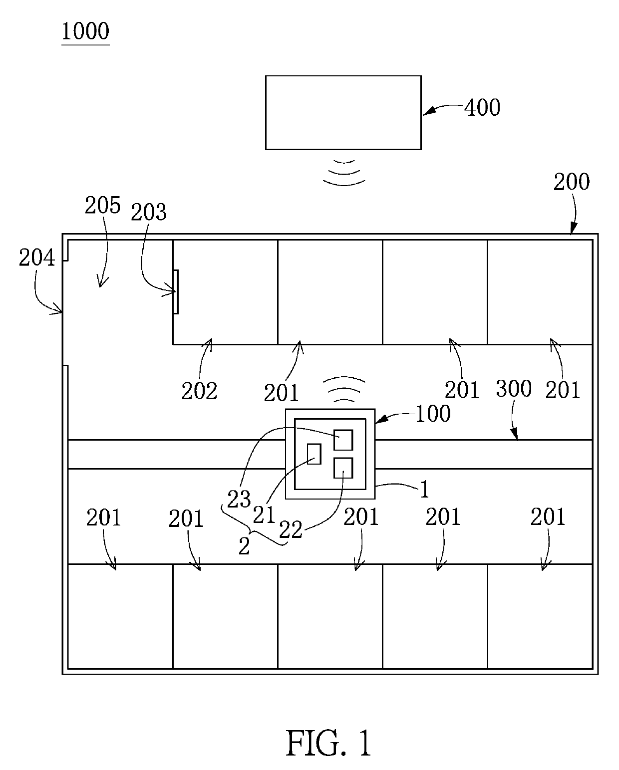
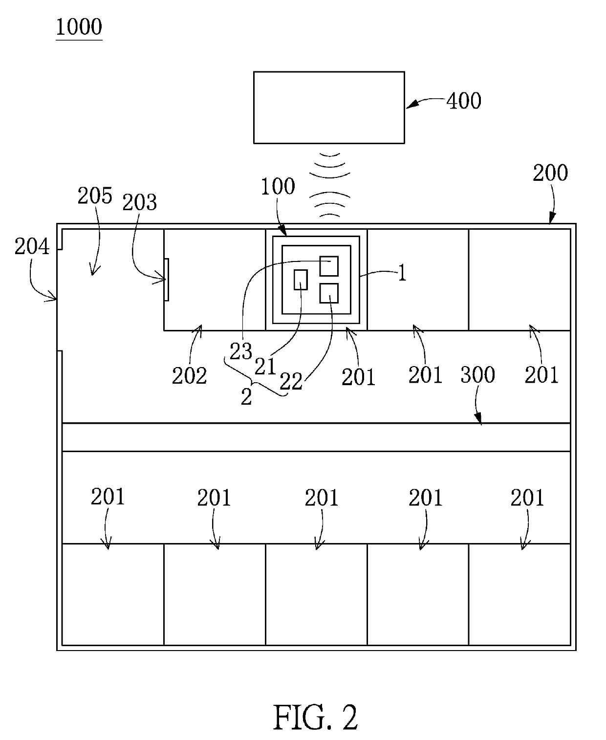
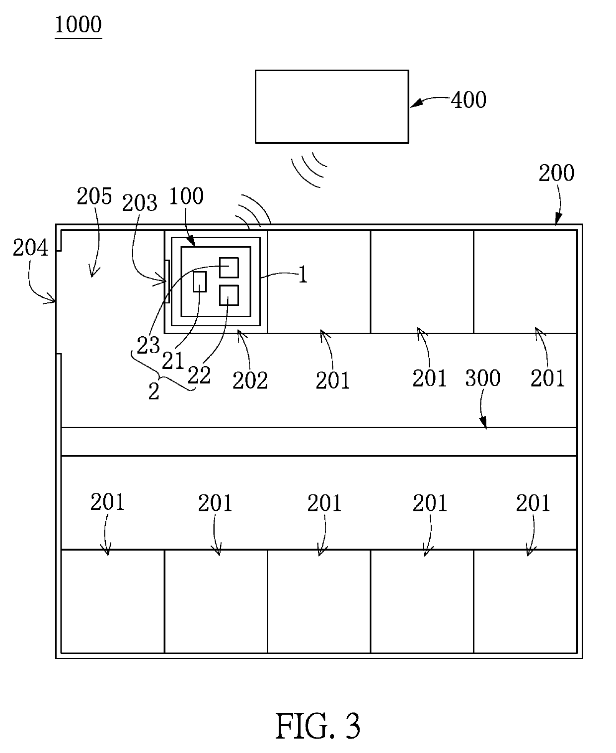
[0024]Reference is first made to FIGS. 1 to 3, which illustrate a particle counter system 1000 of the present embodiment. The particle counter system 1000 in the present embodiment is preferably applied to a panel factor, but the present disclosure is not limited thereto. The particle counter system 1000 includes a stock room 200, a transporting apparatus 300, a detecting apparatus 100, and a controlling apparatus 400. It should be noted that the detecting apparatus 100 can be independently used or can be applied to other systems, that is to say, the detecting apparatus 100 in the present disclosure is not limit...


PUM

PropertyMeasurementUnit
rotating angleaaaaaaaaaa
distanceaaaaaaaaaa
concentrationaaaaaaaaaa

Abstract

A detecting apparatus includes a detecting carrier and a detecting device. The detecting carrier can be moved into a charging frame or anyone of storing frames of a stock room. The detecting device is installed in the detecting carrier and includes a power module and a detector for volatile organic compounds (VOC). The power module is configured to supply power for operating the detecting apparatus. The detector includes a chassis, a displacement unit disposed in the chassis, a detecting unit disposed on the displacement unit, and a blowing unit disposed on the chassis. The detecting unit is configured to detect a concentration of VOC corresponding in position to the detecting carrier. The detecting unit can be arranged inside or outside the chassis by using the displacement unit. The blowing unit is configured to blow VOC adhered to the detecting unit.

Description

BACKGROUND OF THE INVENTION1. Field of the Invention[0001]The present disclosure relates to a detecting apparatus; in particular, to a detecting apparatus and a volatile organic compound (VOC) detector for detecting volatile organic compounds.2. Description of Related Art[0002]A conventional detecting apparatus can be used to automatically detect particles in a stock room which is located between two working stations of a panel factory for transiting or temporarily storing semi-finished products, so that the semi-finished products can be confirmed being located in a clean space environment. However, the conventional detecting apparatus is provided without any VOC detector, so that the conventional detecting apparatus cannot be used to detect volatile organic compounds. In addition, after a conventional VOC detector runs a detecting process, the conventional VOC detector cannot remove the volatile organic compounds adhered thereto by itself, so that the follow-up detecting process of...

Claims


Application Information

Patent Timeline
Patent Type & Authority Patents(United States)
IPC IPC(8): G01N33/00G01D11/02
CPCG01N33/0049G01N33/0029G01N33/0047Y02A50/249Y02A50/235G01D11/02G01D21/02G01N33/00Y02A50/20
Inventor WANG, JING-TANG
Owner MIRLE AUTOMATION CORPORATION
Learn More