Synchronous rectifier with dead time adjusting function

a technology of dead time adjusting and synchronous rectifiers, which is applied in the direction of electric variable regulation, process and machine control, instruments, etc., can solve the problems of increasing the use rate of transistors qb>2/b>, easy burning up of transistors qb>2/b>, and increasing switching losses, so as to reduce the cost, improve the drawbacks, and shrink the product volume

Inactive Publication Date: 2005-08-18
NIKO SEMICON
View PDF2 Cites 23 Cited by
  • Summary
  • Abstract
  • Description
  • Claims
  • Application Information

AI Technical Summary

Benefits of technology

[0009] The present invention provides a synchronous rectifier with a dead time adjusting function, and the adjusted dead time is fixed to improve the drawbacks made by the unstable dead time. Furthermore, the synchronous rectifier with adjusting dead time function may be integrated into an IC (integrate circuit) to shrink the product volume and reduce its cost.
[0012] The present invention may adjust the dead time of circuit switch states and fix the dead time by regulating R and C values of the circuit. Therefore, dead time is not influenced by the unstable duty cycle of the pulse width modulation and the unstable dead time will be improved.

Problems solved by technology

In prior art fly-back power supply, the duty cycle of the pulse width modulation for controlling DC output voltage is not fixed and it may worsen the use rate of the transistor Q2.
The switching loss will be more serious when the circuit is operated with high output voltage, and the transistor Q2 will be burned up easily.
Dead time is not stable and changes with the variation of the supply voltage of the primary side in the above-mentioned fly-back type power supply.
The dead time lasts longer when the supply voltage is low; therefore, the utilization rate of the synchronous switch is worse.
Because the current comparator is made of an iron core and a coil, it cannot be used in integrated circuits.

Method used


Image

  • Synchronous rectifier with dead time adjusting function
  • Synchronous rectifier with dead time adjusting function
  • Synchronous rectifier with dead time adjusting function

Examples


Embodiment Construction

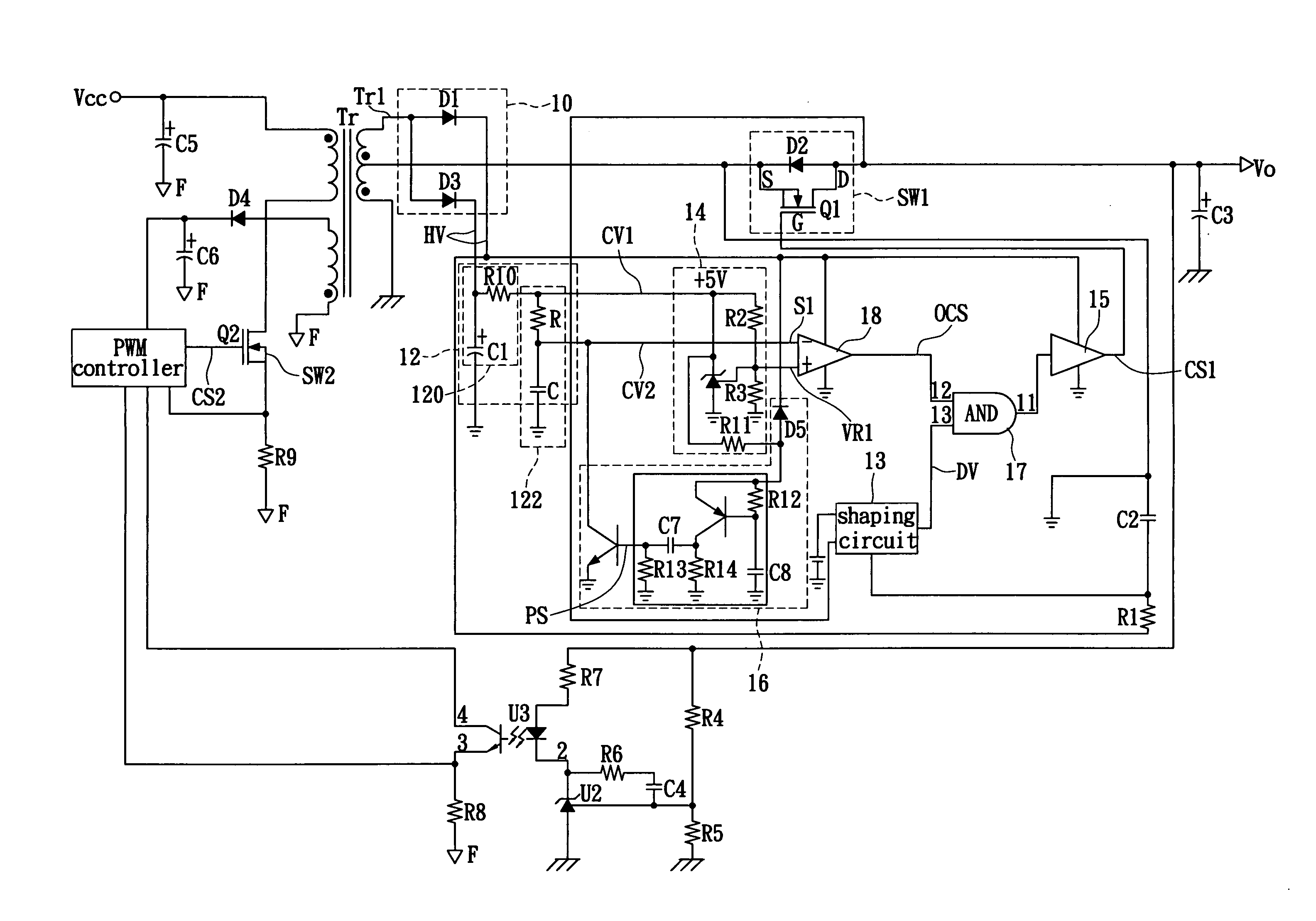
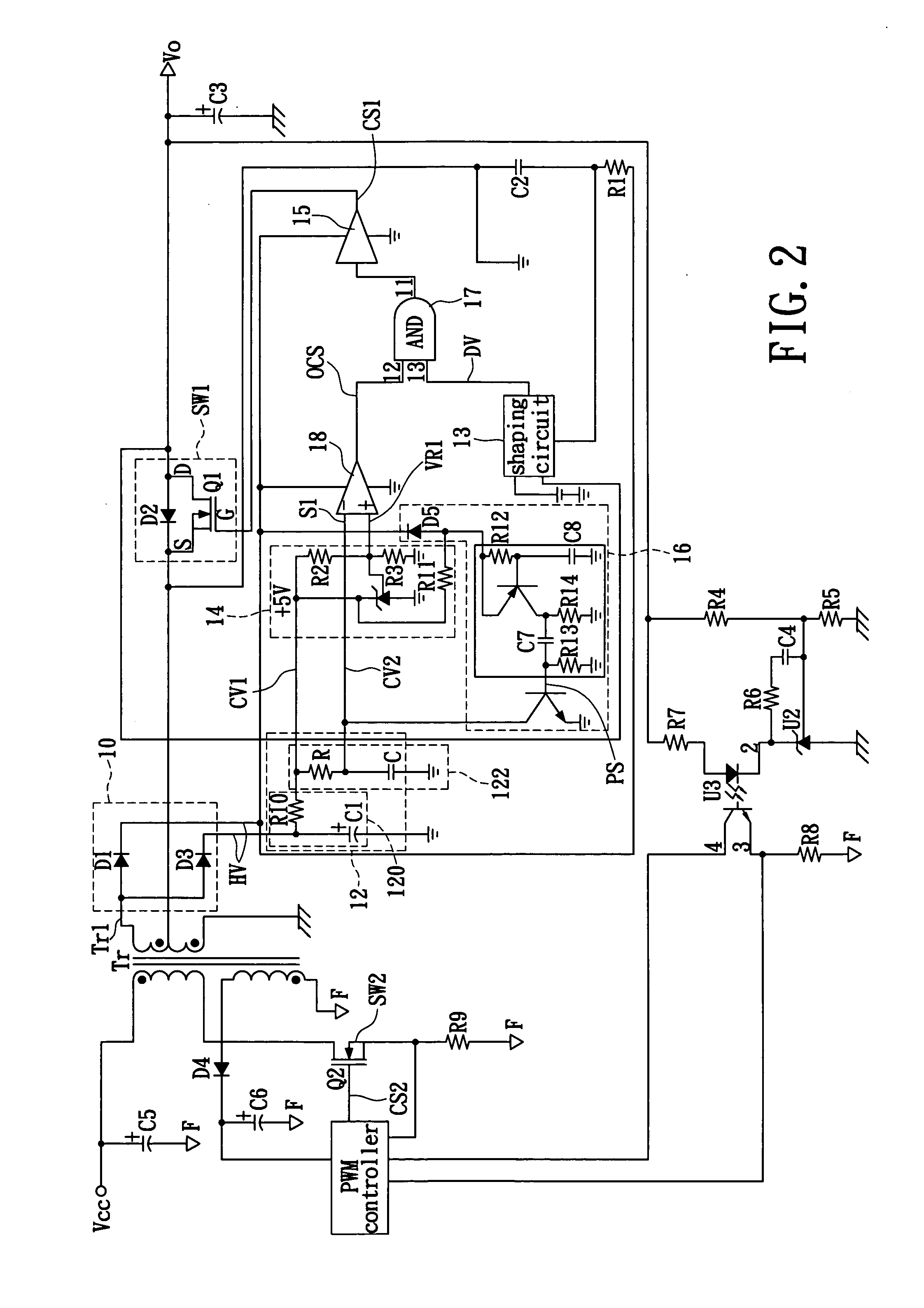
[0019] Reference is made to FIG. 2; it shows a fly-back power supply of the present invention. The fly-back power supply according to the present invention is connected to a secondary side Tr1 of a transformer Tr, a capacitor C3, an output power source Vo and a first electric switch SW1. The fly-back power supply also comprises a rectifying circuit 10, a charging circuit 12, a power-regulating circuit 14, a trigger circuit 16, a comparing circuit 18 and a logic circuit 17.

[0020] The rectifying circuit 10 is connected to the secondary side terminal Tr1 of the transformer Tr, which rectifies an alternating voltage of the secondary side terminal Tr1 into a positive half-cycle voltage HV and transmits the positive half-cycle voltage HV to the rectifying circuit 10 and the charging circuit 12. The charging circuit 12 includes a first charging unit 120 and a second charging unit 122. The first charging unit 120 is connected to the rectifying circuit 10 and charged by the positive half-cy...


PUM


Abstract

A synchronous rectifier with dead time adjusting function is used in fly-back power supplies for adjusting dead time of switches. The synchronous rectifier has a rectifying circuit connected to a secondary side terminal of a transformer and outputting a positive half-cycle voltage, a charging circuit connected to the rectifying circuit for producing a first charging voltage and a second charging voltage, a regulated power circuit connected to the charging circuit and producing a reference voltage, a trigger circuit connected to the rectifying circuit and the charging circuit for generating a dead time adjusting comparing signal, a comparing circuit connected to the regulated circuit, the charging circuit and the trigger circuit for producing a dead time adjusting signal, and a logic circuit connected to the comparing circuit and the rectifying circuit for outputting a driving signal for controlling on / off states of a first electric switch.

Description

BACKGROUND OF THE INVENTION [0001] 1. Field of the Invention [0002] A synchronous rectifier with dead-time adjusting function especially relates to a synchronous rectifier using fly-back power supply. [0003] 2. Description of Related Art [0004] Most of prior art direct current power supplies, for example, AC to DC switching power supply, use high-frequency pulse width modulation (PWM) for shrinking the volume of a transformer. FIG. 1 shows a circuit schematic diagram of a prior art fly-back power supply. The circuit of a transformer T1 is divided into a front-stage circuit 101 at a primary side and a back-stage circuit 102 at a secondary side. Optical signals transferred between the primary side and the secondary side are separated by a photo transistor 111 and a photodiode 112, and changes of the current and the voltage of the secondary side can be fed back to the primary side by optical signals. Therefore, the changes of the current and the voltage in the primary side 101 and the ...

Claims


Application Information

Patent Timeline
Patent Type & Authority Applications(United States)
IPC IPC(8): H02M3/335
CPCH02M3/33569
Inventor YANG, HUI CHIANG
Owner NIKO SEMICON
Why Eureka
Try Eureka