Duplex saw

a dual-bladed saw and saw blade technology, applied in the field of electric cutting tools, can solve the problems of reducing cutting precision, inclined cutting, and above-ground solutions, and achieve the effect of ensuring the stability and reliability of the saw blad

Active Publication Date: 2019-11-19
ZHENGYANG IND & INVESTMENT CO LTD
View PDF15 Cites 0 Cited by
  • Summary
  • Abstract
  • Description
  • Claims
  • Application Information

AI Technical Summary

Benefits of technology

[0007]To overcome the above drawbacks of a duplex saw in the prior art, the present invention aims at providing a duplex saw with a simple and reasonable structure, flexible and easy operation of functional conversion, safe and reliable use, big cutting capacity, high cutting accuracy, and good dust removing effect.
[0016]With the above structure, compared with the prior art, the present invention has the following advantages and effects: first, as the gear box can be rotated around the motor gear shaft, if the gear box is rotated, the function switching between a miter working mode and a cutting working mode can be realized, a working mode is a miter working mode when the output shaft is below the gear shaft of the motor, the working mode is the miter working mode when the output shaft is above the gear shaft of the motor, under the same transmission ratio, a center distance between the output shaft and the gear shaft of the motor can be changed via the middle gear, thus being capable of effectively improving the cutting capacity of the inclined cutting and the cutting. Second, the gear box can be tightly attached to the machine frame via the locking pinch plate of the locking mechanism and forms a fixed connection, thus ensuring the stability and reliability of the saw blade during the work and the cutting accuracy. Third, the conversion shield on the gear box body can completely cover the saw blade exposed on the cutting working platform during the inclined cutting and the saw blade exposed under the cutting working platform during the cutting, thus ensuring the safety and reliability. Fourth, the conversion shield constitutes the dust removing structure with the dust collecting channel via the dust guiding hinged plate during the cutting, the dust removing structure utilizes cutting airflow of the saw blade to discharge sawdust from a dust collecting port of the dust collecting channel to a dust collecting bag, thus solving the problem of dust flying and difficult collection of the duplex saw in the prior art during the cutting.

Problems solved by technology

The above two solutions are flawed in use.
For the first solution, during the process of adjusting the height of the cutting working platform, the relative position between a panel of the cutting working platform and the saw blade can be changed, in order to ensure a smooth height adjustment, a guiding mechanism generally has a relative large gap and maintains poorly the stability of a relative position, thus greatly reducing the precision of the cutting. since the relative position between the motor and the saw blade is fixed, the thickness of the motor in the vertical direction determines the cutting ability of the cutting and the inclined cutting in height; in fact, most manufacturers make a very flat motor assembly, which can slightly increase the cutting height of the cutting and the inclined cutting, however, this is very detrimental to the design of the motor and a motor shell.
Regardless of which solution used, the saw blade in a non-work area in the technical solution in the prior art is exposed, it is difficult to control complete protection, when the cutting is carried out in the non-work area, the non-work area is below the platen while the non-work area is above the platen during the inclined cutting, based on safety requirements, the saw blade in the non-work area needs be completely protected. therefore, it is common practice to add an additional shield in the non-work area as an attachment for protection, special measures need be taken to prevent the attachment from being discarded, so the structure is complicated and inconvenient to operate.
For the above problems, many manufacturers and people of insight have carried out development and research, but so far no more ideal product is available.

Method used


Image

  • Duplex saw
  • Duplex saw
  • Duplex saw

Examples


Embodiment Construction

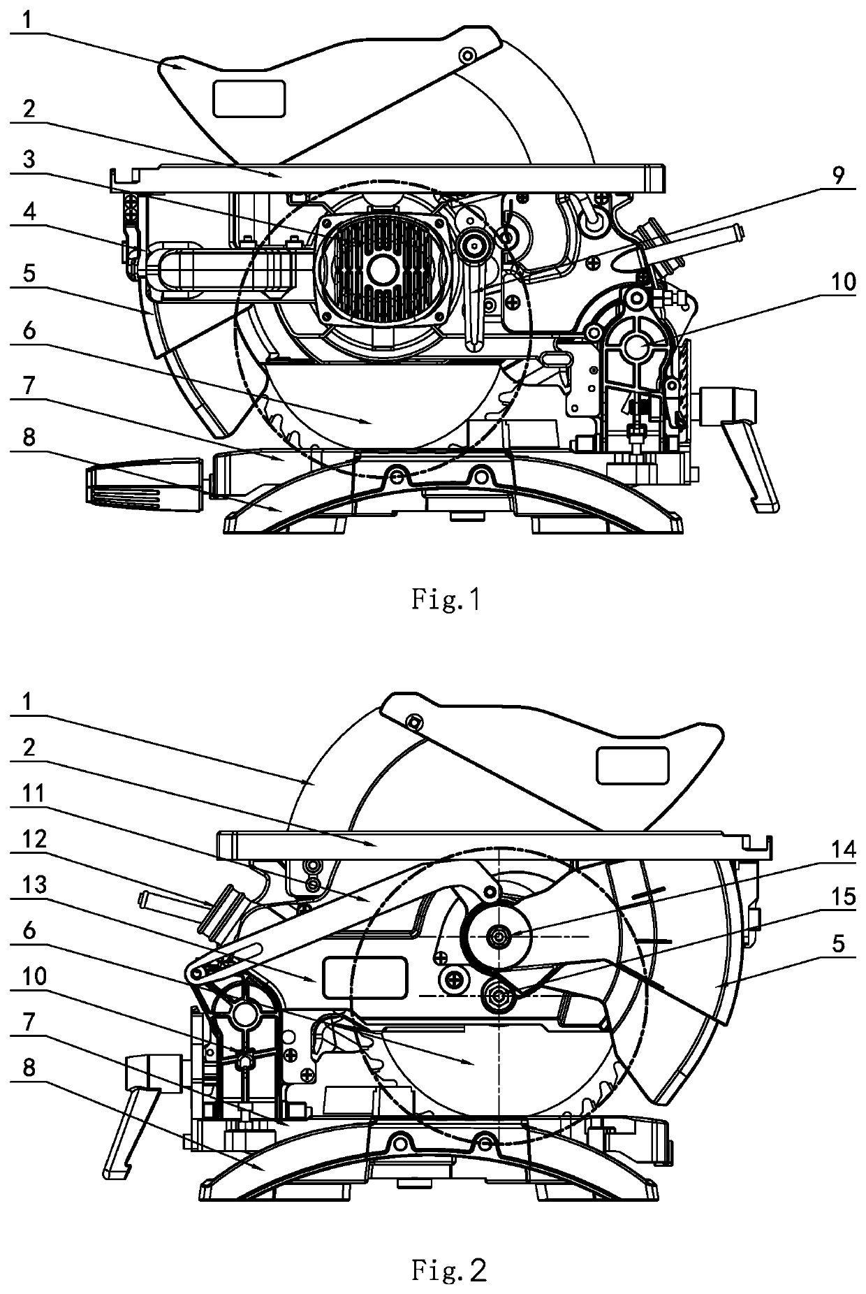
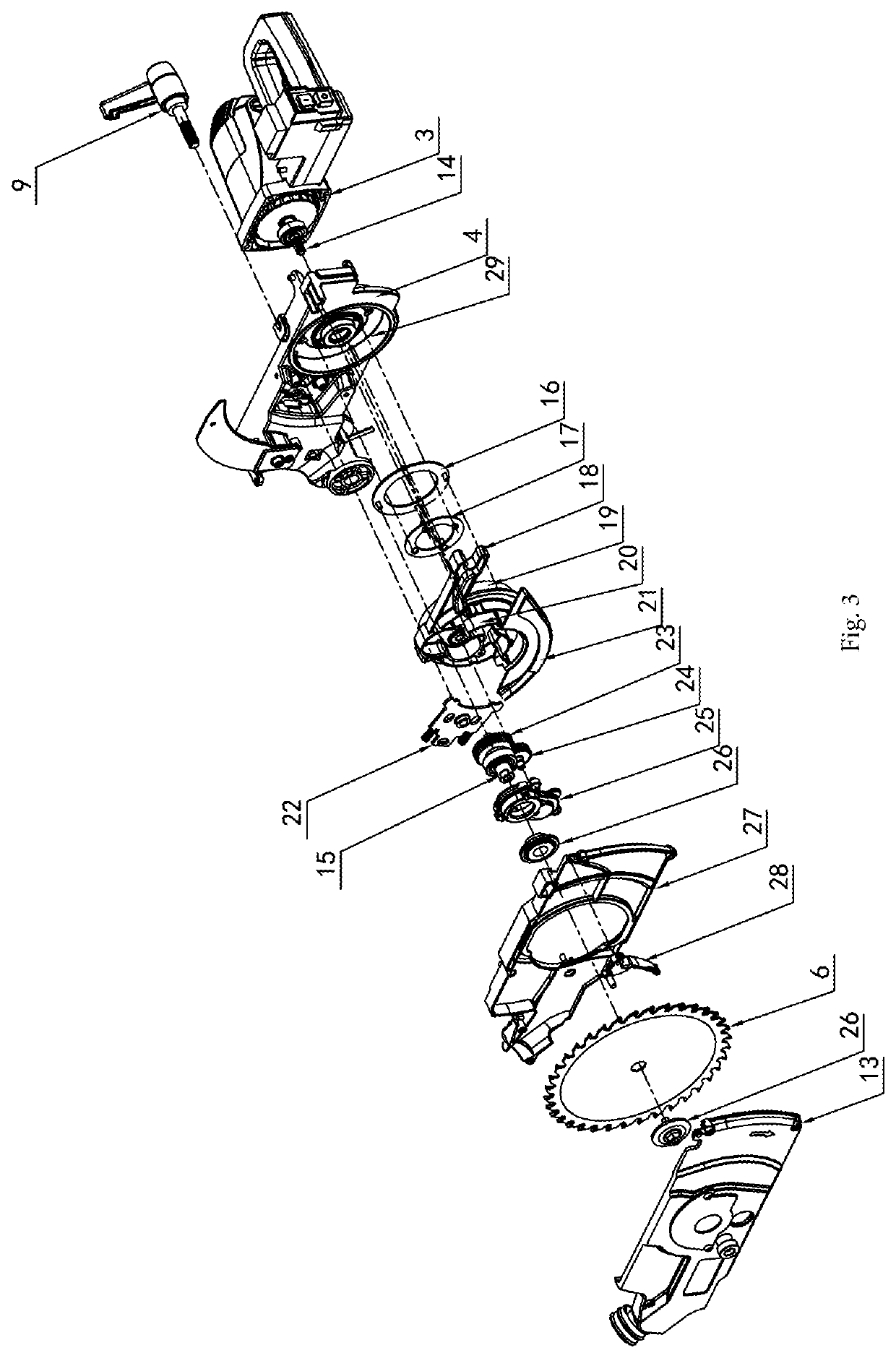
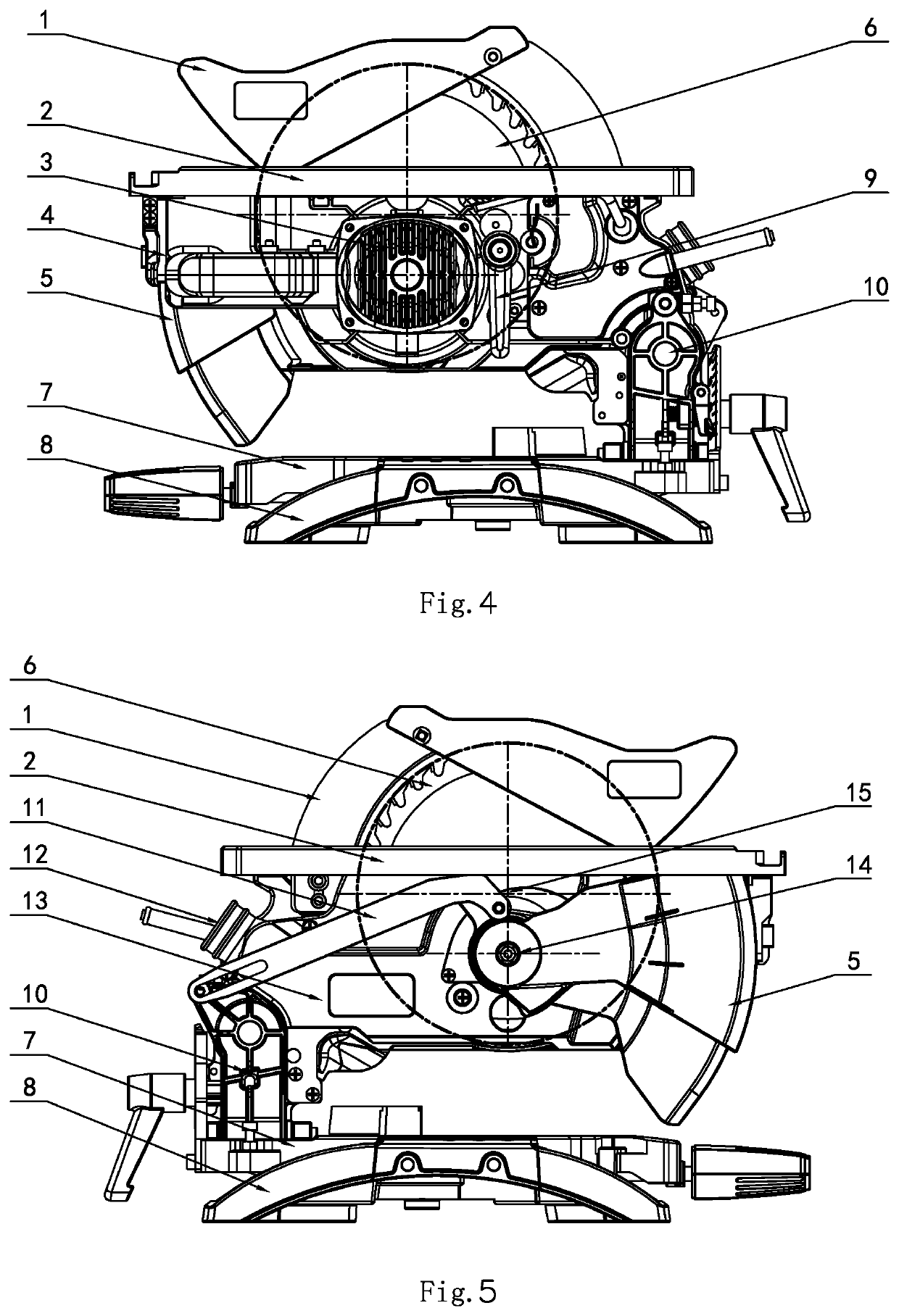
[0025]FIGS. 1-7 show embodiments of a duplex saw of the present invention, the duplex saw comprises a machine head assembly of which a top portion is mounted with a table cutting working platform 2, a base 8, a rotating disk 7, a machine head rotating seat 10 positioned between the machine head assembly and the rotating disk 7 and hinged with the machine head assembly and the rotating disk 7 respectively, and a connection rod assembly 11, wherein the machine head assembly comprises a motor 3, a machine frame 4, a gear box body 20, a transmission mechanism and a saw blade 6, the motor 3 is fixed on the machine frame 4, a gear box cover is fixed on the gear box body 20, the transmission mechanism is provided in the gear box body 20 and constitutes a gear box assembly, a gear shaft 14 of the motor drives the transmission mechanism to be rotated, the gear box assembly can be rotated about the gear shaft 14 of the motor, the saw blade 6 is fixed on an output shaft 15 of the transmission ...


PUM

PropertyMeasurementUnit
heightaaaaaaaaaa
stabilityaaaaaaaaaa
thicknessaaaaaaaaaa

Abstract

A duplex saw, including a machine head assembly of which a top portion is mounted with a cutting working platform, a base, a rotating disk, and a machine head rotating seat positioned between the machine head assembly and the rotating disk and hinged with the machine head assembly and the rotating disk. The machine head assembly includes a motor, a machine frame, a gear box body, a transmission mechanism and a saw blade. The motor is fixed on the machine frame. The transmission mechanism is provided in the gear box body and constitutes a gear box assembly. A gear shaft of the motor drives the transmission mechanism. The gear box assembly can be rotated about the gear shaft of the motor. The blade is fixed on an output shaft of the transmission mechanism, the output shaft and the gear shaft of the motor are parallel to each other.

Description

FIELD OF THE INVENTION[0001]The present invention relates to an electric cutting tool, and more particularly to a duplex saw capable of switching between a table saw working mode and a miter saw working mode.BACKGROUND OF THE INVENTION[0002]A duplex saw is a commonly used power tool and widely used in the field of machinery manufacturing and other fields. The duplex saw can be functionally converted between the two working states of a miter saw and a table saw, and is very convenient to use. There are two commonly used solutions in the prior art: one is a commonly used duplex saw structure, generally, the height of a motor and a saw blade are fixed, the function of sawing is achieved by adjusting the height of a cutting working platform; the other is that a panel of the cutting working platform is fixed, the lift of the saw blade is achieved by lifting or rotating a motor assembly to realize the function of cutting.[0003]The above two solutions are flawed in use. For the first solut...

Claims


Application Information

Patent Timeline
Patent Type & Authority Patents(United States)
IPC IPC(8): B23D45/06B23D45/04B23D47/12B23D59/00B27G19/04B27B9/02
CPCB23D47/12B23D45/04B23D45/065B23D59/006B27G19/04B27B9/02B27B5/165
Inventor XU, KESONG
Owner ZHENGYANG IND & INVESTMENT CO LTD
Why Eureka
Try Eureka