
Catheter assembly

a catheter and needle retraction technology, applied in the direction of catheters, infusion needles, guide needles, etc., can solve the problems of inability to perform secondary user actions, user neglecting to press the activation button or failing to perform the secondary user action, and the use of needle tips covered in blood being undetected from the body of patients, so as to prevent needle re-exposure, improve needle protection and needle retraction, the effect of reducing blood exposur

Active Publication Date: 2019-12-10
BECTON DICKINSON & CO
View PDF29 Cites 0 Cited by
  • Summary
  • Abstract
  • Description
  • Claims
  • Application Information

AI Technical Summary

Benefits of technology

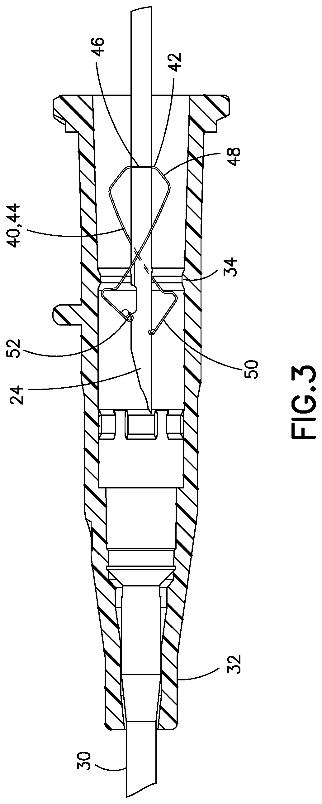
[0005]It is an aspect of the present invention to provide a catheter assembly that incorporates both an active and passive system in a needle protection mechanism. Such a catheter assembly remedies the disadvantages above and improves needle protection and needle retraction. Specifically, the needle tip is enclosed by a spring clip and the needle is retracted into the barrel assembly. In this manner, if the user forgets to press the activation button, the distal tip is already protected by the spring clip. When the activation button is depressed, the needle and the spring clip retract into the barrel assembly, thereby protecting the user from all hazards. Accordingly, the catheter assembly advantageously prevents needle re-exposure and reduces blood exposure.
[0006]It is another aspect of the present invention to provide a controlled variable retraction speed of the needle into the barrel assembly of the catheter assembly. Such a catheter assembly advantageously provides slow needle retraction at the beginning and at the end of the needle travel to reduce blood splatter and provide smooth movement of the needle during retraction. A speed damping profile is advantageously used to control the speed of the needle retraction.
[0010]The foregoing and / or other aspects of the present invention can further be achieved by providing a catheter assembly including a catheter carried by a catheter adapter, a needle having a sharp distal tip and disposed in the catheter such that in a first needle position, the needle extending beyond the catheter, a needle hub fixed adjacent to a proximal end of the needle and fixed to a damping mechanism, a clip being disposed in the catheter adapter, the clip cooperating with the needle, and a barrel assembly surrounding the needle hub, the barrel assembly including first, second and third inner diameters, wherein when the needle is in a second needle position, the clip encloses the distal tip of the needle, and when the needle moves to a third needle position, the needle is retracted into the barrel assembly via spring force from a spring, friction between the damping mechanism and the first inner diameter slows initial movement of the needle hub in the barrel assembly, clearance between the damping mechanism and the second inner diameter provides faster movement of the needle hub in the barrel assembly, and friction between the damping mechanism and the third inner diameter slows movement of the needle hub to a resting position at a proximal end of the barrel assembly.
[0011]The foregoing and / or other aspects of the present invention can also be achieved by providing a catheter assembly including a catheter carried by a catheter adapter, a needle having a sharp distal tip and disposed in the catheter such that in a first needle position, the needle extending beyond the catheter, a needle hub fixed adjacent to a proximal end of the needle and fixed to a first damping mechanism, a clip being disposed in the catheter adapter, the clip cooperating with the needle, a barrel assembly surrounding the needle hub, the barrel assembly including first and second inner diameters, a spring disposed between the barrel assembly and the needle hub, and a second damping mechanism disposed at a proximal end of the spring, wherein when the needle is in a second needle position, the clip encloses the distal tip of the needle, and when the needle moves to a third needle position, the needle is retracted into the barrel assembly via spring force from the spring, friction between the second damping mechanism and the spring slows initial movement of the needle hub in the barrel assembly, clearance between the first damping mechanism and the first inner diameter provides faster movement of the needle hub in the barrel assembly, and engagement of the first damping mechanism and the second inner diameter slows movement of the needle hub to a resting position at a proximal end of the barrel assembly.
[0012]The foregoing and / or other aspects of the present invention can additionally be achieved by providing a catheter assembly including a catheter carried by a catheter adapter, a needle having a sharp distal tip and disposed in the catheter, a needle hub fixed adjacent to a proximal end of the needle, a proximal end of the needle hub being fixed to a damping mechanism, a clip disposed in the catheter adapter, the clip cooperating with the needle, and a barrel assembly surrounding the needle hub, a proximal end of an inner surface of the barrel assembly including the damping mechanism, wherein when the needle is in a second needle position, the clip encloses the distal tip of the needle, and when the needle moves to a third needle position, the needle is retracted into the barrel assembly via spring force from a spring, and the damping mechanism and the spring slow initial movement of the needle hub in the barrel assembly, and when the needle hub approaches an end of travel, the damping mechanism and the spring slow movement of the needle hub to a resting position at a proximal end of the barrel assembly.

Problems solved by technology

Various disadvantages arise in each of the needle protection mechanisms.
Specifically, in active systems, the user may neglect to depress the activation button or fail to perform the secondary user action to protect the needle.
For example, when the activation button is not depressed, the used needle tip that is covered in blood is undesirably exposed from the body of a patient.
However, these damping mechanisms are not always able to adequately control the retraction speed of the needle.

Method used


Image

  • Catheter assembly
  • Catheter assembly
  • Catheter assembly

Examples


Embodiment Construction

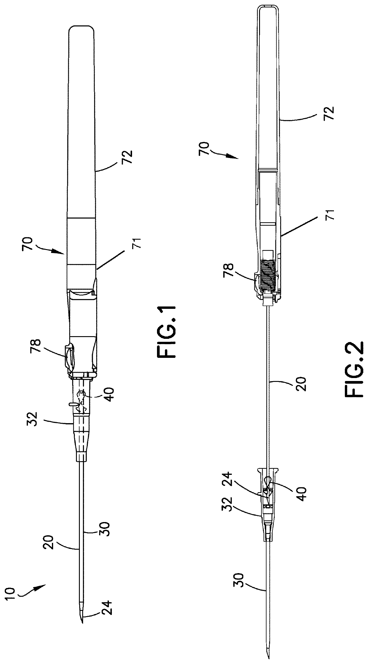
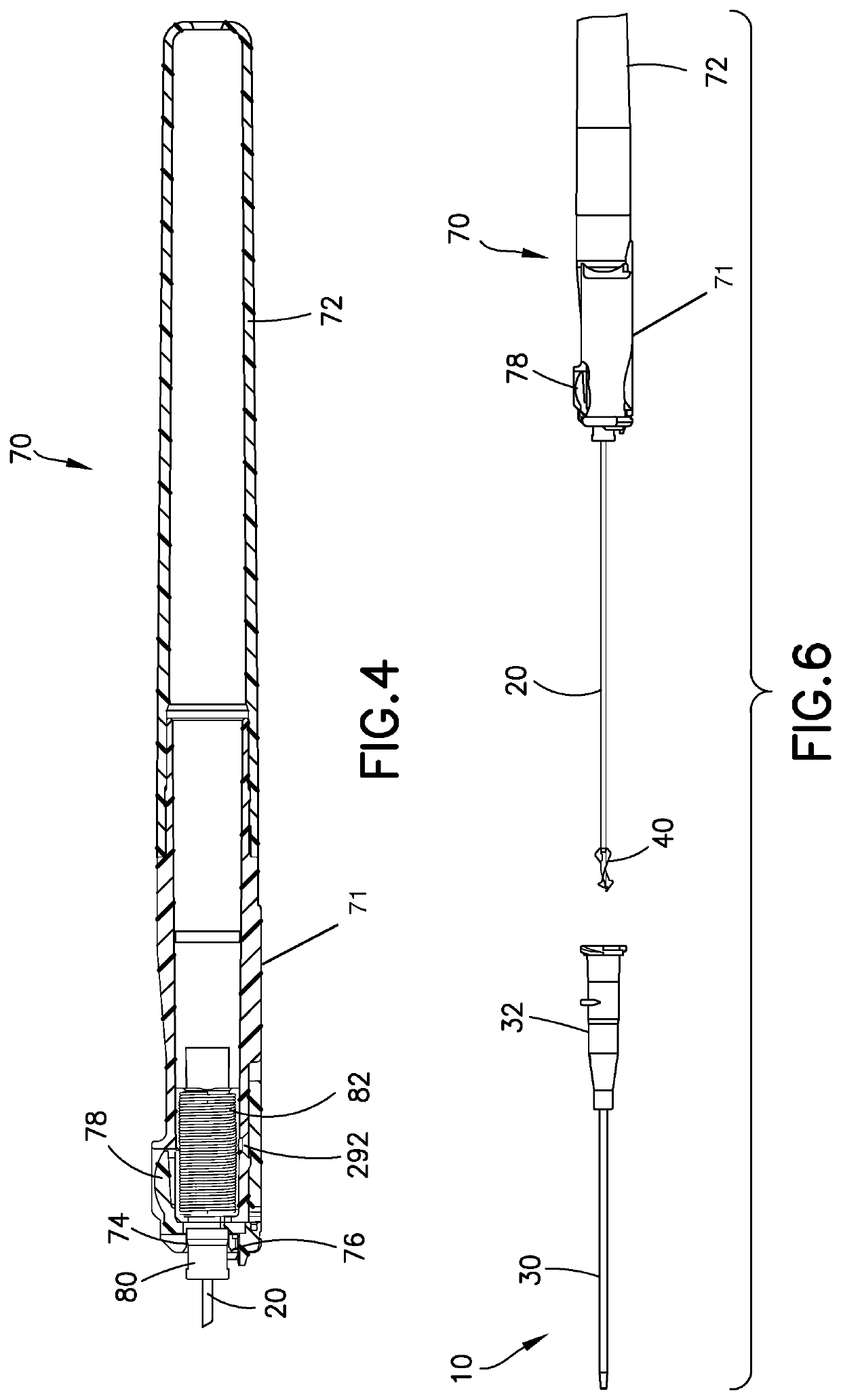
[0038]FIGS. 1-9 illustrate a first exemplary embodiment of a catheter assembly 10. FIG. 1 illustrates the catheter assembly 10 in a first needle position ready for operation. According to one embodiment, the catheter assembly 10 includes a hollow introducer needle 20 having a sharp distal tip 24 for insertion in a skin of a patient. The needle 20 is disposed in a flexible catheter 30. The catheter 30 is used for medication delivery during use of the catheter assembly 10. In the first needle position, the sharp distal tip 24 of the needle 20 extends beyond the catheter 30 for insertion.

[0039]According to one embodiment, the catheter 30 and the needle 20 are carried or surrounded by a catheter adapter 32. FIG. 2 illustrates the needle 20 moving from the first needle position toward a second needle position after the user has placed the catheter 30 in the body of the patient and removed the needle 20 from the patient.

[0040]FIG. 3 illustrates, according to one embodiment, the catheter a...


PUM


Abstract

A catheter assembly including a catheter carried by a catheter adapter, a needle having a sharp distal tip and disposed in the catheter such that in a first needle position, the needle extending beyond the catheter, a needle hub fixed adjacent to a proximal end of the needle, a clip disposed in the catheter adapter and cooperating with the needle, and a barrel assembly including an inner diameter, wherein when the needle is in a second needle position, the clip encloses the distal tip of the needle, and when the needle moves to a third needle position, the clip and the needle is disposed in the inner diameter of the barrel assembly.

Description

FIELD[0001]Various exemplary embodiments of the invention relate to needle protection and needle retraction in catheter assemblies.BACKGROUND[0002]Typical catheter assemblies incorporate one of two types of needle protection mechanisms. An active system is a needle protection mechanism that requires a separate user action to initiate needle protection, such as depression of an activation button to activate automatic and instantaneous needle retraction into a barrel assembly. This action would take place after the needle is withdrawn from a skin of a patient and from the catheter. On the other hand, a passive system is a needle protection mechanism that automatically protects the needle when a user manually retracts the needle from the catheter, typically using a spring clip and without requiring a separate user action. In other words, the needle is immediately protected when it is withdrawn from a skin of a patient and from the catheter.[0003]Various disadvantages arise in each of t...

Claims


Application Information

Patent Timeline
Patent Type & Authority Patents(United States)
IPC IPC(8): A61M25/06A61M25/00A61M39/10A61M5/32
CPCA61M25/0618A61M25/0097A61M25/0631A61M25/0606A61M5/3273A61M39/10A61M2039/1077
Inventor ISAACSON, RAYWILLYBIRO, FIDELIN
Owner BECTON DICKINSON & CO
Learn More