Supercharge Your Innovation With Domain-Expert AI Agents!

Image forming apparatus and program executed by computer of image forming apparatus

a technology of image forming apparatus and image forming device, which is applied in the direction of electrographic process apparatus, corona discharge, instruments, etc., can solve the problems of image memory not being sufficiently prevented, forming potential, and difference between primary charging potential and forming potential, so as to prevent an image memory

Active Publication Date: 2019-12-17
KONICA MINOLTA INC
View PDF7 Cites 2 Cited by
  • Summary
  • Abstract
  • Description
  • Claims
  • Application Information

AI Technical Summary

Benefits of technology

This patent text describes an image forming apparatus that aims to prevent image memory and other related issues. The apparatus includes an image carrier, charging member, charging power supply, exposurer, developing member, developing power supply, transfer member, and hardware processor. The processor analyzes the potential on the image carrier after the toner image has been transferred to the medium and determines the charging bias based on the difference between the potentials of the exposure part and the non-exposure part, ensuring a uniform potential on the image carrier. Thereafter, the developing bias is determined based on the determined charging bias. This allows for a more uniform potential on the image carrier, reducing image memory and improving the quality of the transferred toner image.

Problems solved by technology

However, relative to variation in the resistances of the intermediate transfer member caused by manufacturing errors, there is a possibility that the image memory cannot be sufficiently prevented.
Furthermore, the technique disclosed in JP 2008-008991 A may cause a disadvantage caused by the difference between the primary charging potential and the developing potential difference in a case where “the difference between the primary charging potential of the charging device and the image forming potential of the exposurer” is changed.

Method used


Image

  • Image forming apparatus and program executed by computer of image forming apparatus
  • Image forming apparatus and program executed by computer of image forming apparatus
  • Image forming apparatus and program executed by computer of image forming apparatus

Examples


embodiment

[0042][Embodiment]

[0043](Image Forming Apparatus 300)

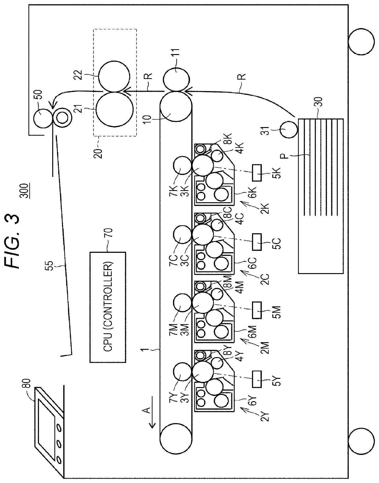
[0044]FIG. 3 is a diagram for explaining an exemplary configuration of an image forming apparatus 300 according to an embodiment. In one embodiment, the image forming apparatus 300 is an electrographic image forming apparatus such as a laser printer and an LED printer. As illustrated in FIG. 3, the image forming apparatus 300 includes the intermediate transfer belt 1 in a substantially center as a belt member. Under a lower horizontal part of the intermediate transfer belt 1, four image forming units 2Y, 2M, 2C, and 2K respectively corresponding to yellow (Y), magenta (M), cyan (C), and black (K) are arranged along the intermediate transfer belt 1. The image forming units 2Y, 2M, 2C, and 2K respectively include photoreceptors 3Y, 3M, 3C, and 3K which can hold the toner image.

[0045]Around the respective photoreceptors 3Y, 3M, 3C, and 3K which are image carriers, along the rotation direction in the following order, charging rollers ...


PUM


Abstract

An electrophotographic image forming apparatus includes: an image carrier that carries and conveys a toner image; a charging member arranged in contact with or close to the image carrier; a charging power supply that charges the image carrier; an exposurer that forms a latent image on the charged image carrier; a developing member arranged close to the image carrier; a developing power supply that develops the latent image and forms a toner image on the image carrier; a transfer member that transfers the toner image to a medium; and a hardware processor that controls the image forming apparatus, wherein the hardware processor obtains a potential of an exposure part and a non-exposure part, on the image carrier after the toner image has been transferred to the medium, determines a charging bias based on a difference between the obtained potentials, and determines a developing bias based on the determined charging bias.

Description

[0001]The entire disclosure of Japanese patent Application No. 2017-207899, filed on Oct. 27, 2017, is incorporated herein by reference in its entirety.BACKGROUNDTechnological Field[0002]The present disclosure relates to an image forming apparatus, and more specifically, to an electrophotographic image forming apparatus.Description of the Related Art[0003]Regarding an electrophotographic image forming apparatus, “image memory” in which non-uniformity of surface potentials of an image carrier according to previous printing affects the current printing has been known. The image memory is a phenomenon which hinders uniformization of an image density.[0004]Regarding a technique for reducing the image memory, for example, JP 2006-017909 A discloses a technique in which “after a surface potential of an image part of an image carrier receives charge injection from an intermediate transfer member at the time of transferring a toner image and changed by the charge means until the procedure p...

Claims


Application Information

Patent Timeline
Patent Type & Authority Patents(United States)
IPC IPC(8): G03G15/16G03G21/08G03G21/00G03G15/00G03G15/043B41J2/385G03G21/06G03G15/02G03G15/06G03G15/047G03G15/045
CPCG03G15/047G03G15/045G03G15/0266B41J2/385G03G15/0283G03G21/0094G03G15/065G03G21/08G03G15/169G03G15/043G03G15/5033G03G15/0275G03G21/06G03G15/02G03G15/5008
Inventor KIMURA, MASATO
Owner KONICA MINOLTA INC
Features
  • R&D
  • Intellectual Property
  • Life Sciences
  • Materials
  • Tech Scout
  • Unparalleled Data Quality
  • Higher Quality Content
  • 60% Fewer Hallucinations
Learn More