Image forming apparatus

a technology of image forming apparatus and forming tube, which is applied in the field of image forming tube, can solve problems such as the upsize of the apparatus, and achieve the effect of reducing the upsize of the image forming tub

Active Publication Date: 2020-01-21
CANON KK
View PDF14 Cites 0 Cited by
  • Summary
  • Abstract
  • Description
  • Claims
  • Application Information

AI Technical Summary

Benefits of technology

[0005]The present invention has been made in view of the above problems and has an object of providing a technology for reducing the upsize of an image forming apparatus while ensuring ventilation from an outside to an environment detection unit provided in the image forming apparatus.
[0017]According to an embodiment of the present invention, it is possible to reduce the upsize of an image forming apparatus while ensuring ventilation from an outside to an environment detection unit provided in the image forming apparatus.

Problems solved by technology

In addition, it is necessary to increase the size of the shielding wall in order to ensure the protection of the environment detection means, and ensuring space for providing the shielding wall results in the upsize of the apparatus.

Method used


Image

  • Image forming apparatus
  • Image forming apparatus
  • Image forming apparatus

Examples


first embodiment

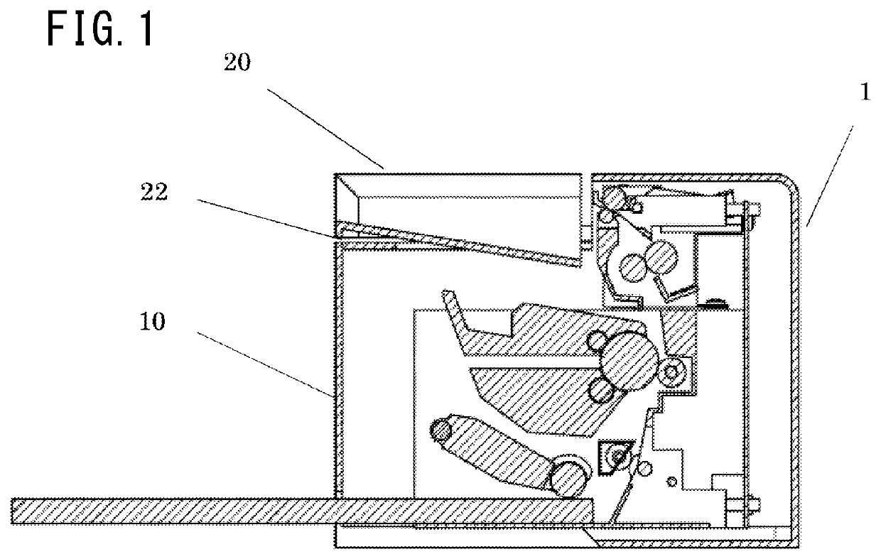
[0033]A first embodiment of the present invention will be described in detail using the drawings. An image forming apparatus according to the first embodiment will be described using a monochrome laser beam printer. Note that the monochrome laser beam printer is an example and an image forming apparatus to which the present invention is applicable is not limited to the example. For example, a color laser beam printer may be used as such.

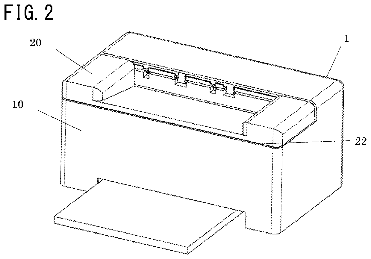
[0034]FIG. 1 is a schematic cross-sectional view illustrating the schematic configuration of an image forming apparatus 1 according to the first embodiment of the present invention. The image forming apparatus 1 includes a housing 10 that serves as an apparatus body and a door 20 that serves as an opening and closing member provided on the housing 10. The door 20 that serves as the opening and closing member is rotatably supported by the housing 10 that serves as the apparatus body. In the present embodiment, the door 20 that serves as the opening an...

second embodiment

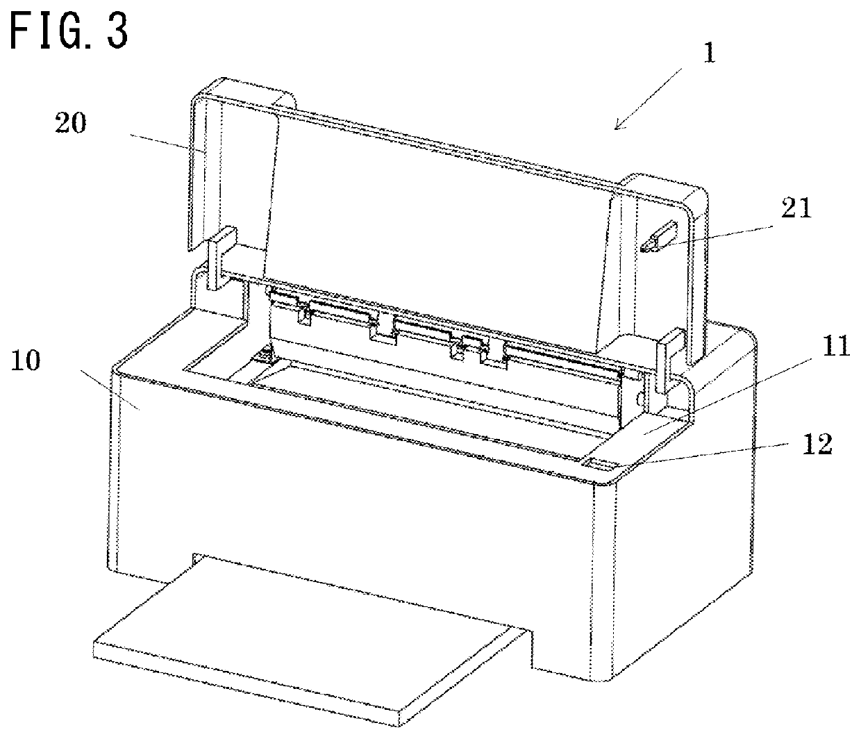
[0058]An example in which the present invention is applied to a configuration in which an opening and closing sensor for a door that serves as an opening and closing member does not have a link will be described as a second embodiment of the present invention. Hereinafter, the descriptions of respects common to the image forming apparatus according to the first embodiment will be omitted, and the difference between the first embodiment and the second embodiment will be mainly described. A state (closed state) in which the door of an image forming apparatus according to the second embodiment is closed is the same as that of the image forming apparatus according to the first embodiment and is illustrated in FIG. 2. Like the first embodiment, there is a gap 22 between a housing 10 and a door 20 in a state in which the door 20 that serves as an opening and closing member is closed. A perspective view illustrating a state (open state) in which the door of the image forming apparatus acco...


PUM


Abstract

Provided is an image forming apparatus in which a movable member comes close to an opening to cover a part of the opening in the open state of an opening and closing member. In the course of change from the open state to the state in which an entering portion enters the inside of the housing, the movable member is pressed by the entering portion to move away from the opening and the opening and closing member moves toward the opening. In the closed state of the opening and closing member, the movable member is placed in a position further away from the opening than in the open state, and the opening and closing member is in the position in which the opening and closing member covers a part of the opening while forming a gap between the opening and closing member and the housing.

Description

BACKGROUND OF THE INVENTIONField of the Invention[0001]The present invention relates to an image forming apparatus.Description of the Related Art[0002]An image forming apparatus conveys a sheet-shaped recording medium such as paper supplied from an outside to an image forming unit provided in the image forming apparatus and forms an image on the recording medium. The status of paper and the behavior of various mechanisms are influenced by an environment under which the apparatus is placed. In view of this, there has been known a technology in which information on an external environment such as temperature and humidity is acquired and fed back to control image formation (Japanese Patent Application Laid-open No. H11-130298). As means for acquiring information on an external environment, environment detection means for detecting temperature, humidity, or the like is provided in an apparatus shielded from an outside (Japanese Patent Application Laid-open No. 2010-169998). In order to ...

Claims


Application Information

Patent Timeline
Patent Type & Authority Patents(United States)
IPC IPC(8): G03G21/20G03G21/16
CPCG03G21/1623G03G21/203G03G21/1633
Inventor HAMASAKI, RYUJISUZUKI, TETSUJI
Owner CANON KK
Why Eureka
Try Eureka