Supercharge Your Innovation With Domain-Expert AI Agents!

Multipoint payload release system

a multi-point, payload technology, applied in the direction of transportation and packaging, ammunition fuzes, cosmonautic vehicles, etc., can solve the problems of limited payloads, melt and break, and limitation of communication channels

Active Publication Date: 2020-02-04
ENSIGN BICKFORD AEROSPACE & DEFENSE
View PDF19 Cites 1 Cited by
  • Summary
  • Abstract
  • Description
  • Claims
  • Application Information

AI Technical Summary

Problems solved by technology

A non-energetic HDRM is one that typically utilizes an activation mechanism such as a fuse wire or link wire that heats and weakens on command from a control unit when an amount of electrical current passes through the wire, thereby causing it to melt and break.
This limitation in the number of communication channels limited the number of payloads that could be deployed from the spacecraft.

Method used


Image

  • Multipoint payload release system
  • Multipoint payload release system
  • Multipoint payload release system

Examples


Embodiment Construction

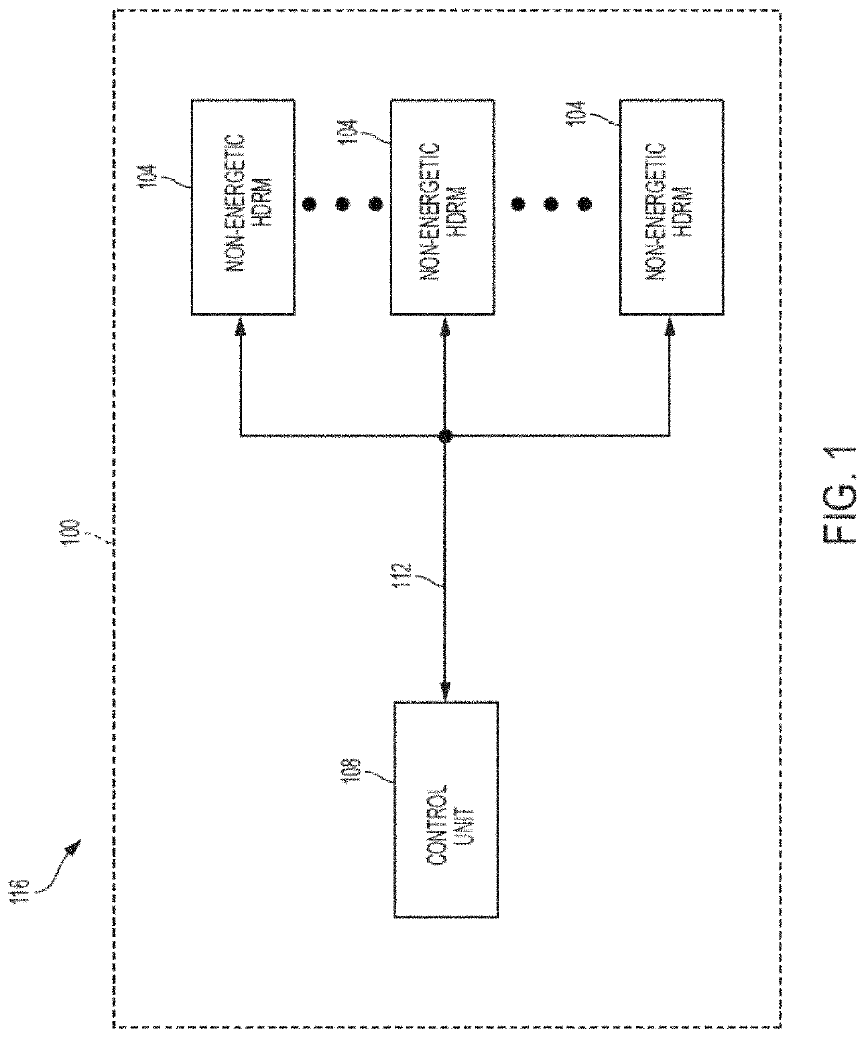
[0040]Referring to FIG. 1, a networked initiation system 100 according to an embodiment of the present disclosure includes one or more (i.e., “at least one”) non-energetic hold-down and release mechanisms (“HDRMs”) 104, a control unit 108, and an interface bus 112 connected between all of the HDRMs 104 and the control unit 108. In some embodiments, the HDRMs 104 and control unit 108 are connected together in a “network” type configuration by the interface bus 112 in the networked initiation system 100. The interface bus 112 allows for two-way communication between any of the HDRMs 104 and the control unit 108 connected by the interface bus 112. As used herein, the term “non-energetic” refers to the HDRMs 104 being primarily non-explosive and / or non-pyrotechnic in nature, as will be appreciated by those of skill in the art.

[0041]The networked initiation system 100 of FIG. 1 may be part of an aeronautical or aerospace type vehicle 116 utilized for travel away from the Earth's surface ...


PUM


Abstract

Networked initiation systems for hold-down and release mechanisms (HDRMs) are described. The systems include a control unit, a plurality of firing control units operably connected to and in communication with the control unit, wherein each firing control unit has at least one HDRM operably connected thereto, and wherein each firing control unit is individually addressable by the control unit over an interface bus to enable selective operation of the HDRMs operably connected to the firing control units.

Description

CROSS REFERENCE TO RELATED APPLICATIONS[0001]This application is a continuation-in-part application of the legally related U.S. patent application Ser. No. 15 / 263,695 filed Sep. 13, 2016, the contents of which are incorporated by reference herein in their entirety.BACKGROUND OF THE DISCLOSURE[0002]The subject matter disclosed herein relates in general to the initiation of devices located on vehicles (e.g., spacecraft, launch vehicle, etc.), and in particular to systems configured to control the initiation of non-energetic and / or energetic hold-then-separate devices located on the vehicle.[0003]Launch vehicles typically have multiple stages and are used to carry payloads during travel away from the Earth's surface after the vehicles are launched, and then place or deploy the payloads into orbit or beyond. These payloads are commonly referred to as satellites if they are intended to orbit a body (e.g., Earth) after deployment, or as spacecraft if they are intended to leave the Earth's...

Claims


Application Information

Patent Timeline
Patent Type & Authority Patents(United States)
IPC IPC(8): B64G1/10F42D1/05B64G1/64F42C15/42
CPCB64G1/641B64G1/10F42C15/42F42D1/05B64G1/645
Inventor NOVOTNEY, DAVIDKACZYNSKI, GEOFFBOUCHER, CRAIG
Owner ENSIGN BICKFORD AEROSPACE & DEFENSE
Features
  • R&D
  • Intellectual Property
  • Life Sciences
  • Materials
  • Tech Scout
  • Unparalleled Data Quality
  • Higher Quality Content
  • 60% Fewer Hallucinations
Learn More