Connector

a technology of connecting rods and connecting rods, which is applied in the direction of pipe joints, pipe laying and repair, mechanical equipment, etc., can solve the problems of screwthreaded engagement between the second part and the said further part becoming jammed, and it is difficult to unscrew, so as to improve the locking and sealing of the connector

Active Publication Date: 2020-02-04
KUTTING UK
View PDF10 Cites 2 Cited by
  • Summary
  • Abstract
  • Description
  • Claims
  • Application Information

AI Technical Summary

Benefits of technology

[0005]Accordingly, a first aspect of the present invention is directed to a connector comprising a cylindrical sleeve device having a first part, with an external screwthread on its outer side, and a second part, with an internal screwthread on its inner side, one of the screwthreads engaging a corresponding screwthread on a further part when the connector is in use, at least a portion of the said second part being yieldable, the connector further comprising a locking part provided with a screwthread which engages the other of the screwthreads of the cylindrical sleeve device when the connector is in use, the said second part and the locking part having mutually engageable portions which, when the locking part is tightened relative to the cylindrical sleeve device, interengage to cause yielding of the second part or yieldable portion thereof and so effect locking of the cylindrical sleeve device with respect to such a further part when the connector is in use.
[0009]Of the pair of screwthreads of the first part and the locking part on the one hand, and the pair of screwthreads of the second part and the said further part on the other hand, one of those pairs is “left-handed” and the other of those pairs is “right-handed”, although convention dictates that it is the pair of screwthreads of the second part and the said further part that are “right-handed”. Such an arrangement of opposing screwthreads assists the jamming between the second part and the further part, especially because during a final tightening of the locking part with respect to the first part, a user may inadvertently apply contra-rotation to the further part. Such an arrangement of opposing screwthreads reduces the likelihood of any inadvertent contra-rotation, because tightening of the locking part and the first part operates in the same sense as would further tighten the second part with respect to the further part of the cylindrical sleeve device.
[0016]A stress widening or stress hole is intended to mitigate the effects of stress and strain, reducing the risk of cracking of the material.
[0020]Thus, in an embodiment in which the said first and second parts are separable, a single slot may be provided along substantially the full length of the second part substantially parallel to the axis thereof. This arrangement enables substantially the whole of the second part to be yieldable, thus providing a large surface area for frictional engagement between the second part and the said such a further part.
[0027]The angle of tapering of these corresponding tapered surfaces may be shallow, for example the tapered surface may be in the range of approximately 15° to 25°, preferably approximately 20°, to an axis of the respective part. A shallow tapering angle aids the formation of a frictional lock between corresponding surfaces of the locking part and the cylindrical sleeve device, and also urges the parts together, thus further improving the locking and sealing of the connector.
[0028]The second part may be provided with a further tapered or chamfered surface in the region of its end nearest the first part, the surface corresponding to a corresponding tapered surface provided on the first part which abuts the said further tapered or chamfered surface when in use. The angle of incline relative to the common axis of the first and second parts of these abutting surfaces may be relatively high in comparison with the tapering of the engaging surfaces of the second part and the locking part. Such a relatively steep tapering or chamfering, in a range of approximately 30° to 50°, preferably 40°, to the common axis, assists the formation of an axial lock between the first and second parts.

Problems solved by technology

In use, yielding of the second part or a portion thereof provides a frictional engagement between the second part and the said such a further part, as well as causing a displacement of the screwthread of the second part relative to the screwthread of the said such further part, so that the screwthreaded engagement between the second part and the said such further part may become jammed and thus difficult to unscrew.

Method used


Image

  • Connector
  • Connector
  • Connector

Examples


Embodiment Construction

[0065]In the detailed description below, some features described may not appear or be labelled in every drawing, for the purpose of clarity, but the context of the description will enable the skilled person to identify when a feature is present but which is not shown in a particular Figure, or which is shown but not explicitly labelled.

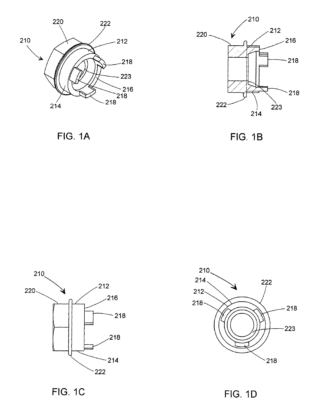
[0066]FIGS. 1A, 1B, 1C, and 1D show a tubular or hollow cylindrical first part 210 of a cylindrical sleeve device of a connector, the first part 210 having a region 212 having a screwthread 214 formed on an external surface. Protruding parallel to an axis of the first part 210 from a front end 216 of the first part 210 are three substantially equiangularly spaced tongues 218. At a rear end 220 of the first part 210 the external surface is hexagonal. The region 212 has a screwthread 214 on its external surface. Between the region 212 and the rear end 220 there is a flanged portion 222 of slightly larger diameter than that of the region 212 and that of ...


PUM


Abstract

A connector has a cylindrical sleeve device having a first part, with an external screwthread on its outer side, and a second part, with an internal screwthread on its inner side. One of the screwthreads engages a corresponding screwthread on a further part when the device is in use. At least a portion of the said second part is yieldable. A locking part is provided with a screwthread which engages the other of the screwthreads of the cylindrical sleeve device when the connector is in use. The second part and the locking part have mutually engageable portions which, when the locking part is tightened relative to the cylindrical sleeve device, interengage to cause yielding of the second part or yieldable portion thereof. This effects locking of the cylindrical sleeve device with respect to such a further part when the connector is in use.

Description

TECHINICAL FIELD[0001]The present invention is directed to a connector especially but not exclusively for connecting subsea hose.CROSS REFERNCE TO RELATED APPLICATIONS[0002]This application is the National Stage of International Application PCT / GB2015 / 000057 filed Feb. 16, 2015, which claims the benefit of United Kingdom Patent Application No. 1409922.0 filed on 4 Jun. 2014, the specification of which is incorporated by reference.BACKGROUND[0003]Subsea hoses are subjected to a wide range of forces, especially flexural and rotational forces, as well as internal pressure and external pressure, during and after installation, for periods of 20 years or more. Once installed, it is desirable for subsea hoses to remain in situ for many years. Furthermore, it is desirable for connections between for example subsea hoses and stab connector boxes to be capable of maintaining a sealed connection under sustained and repeated such subsea forces. Such a seal is desirably to be maintained for many...

Claims


Application Information

Patent Timeline
Patent Type & Authority Patents(United States)
IPC IPC(8): F16L19/02F16L1/26F16L19/00F16L19/025
CPCF16L19/025F16L19/0206F16L19/005F16L1/26
Inventor SHORROCK, LEE PETERJOHNSON, KEVINSHORROCK, PETER
Owner KUTTING UK
Why Eureka
Try Eureka