
Safety Connecting Device, In Particular For Piping, An End-Coupler For Such Device, And A Method For Manufacturing A Nut Therefor

Active Publication Date: 2015-01-29
JPB SYST
View PDF17 Cites 5 Cited by
  • Summary
  • Abstract
  • Description
  • Claims
  • Application Information

AI Technical Summary

Benefits of technology

The technical effects of this patent are as follows: 1. The invention includes a nut and a second end-coupler with axial bearing means to limit the axial displacement of the nut with respect to the second end-coupler in the nut screwing direction. This allows for better locking and a high thickness of material to be retained in the tubular body equipped with tabs, as well as high robustness to this tubular body accordingly. 2. The invention suppresses the need for manufacturing a further component equipped with tabs, and installing this further component into a tubular body. The patent describes a design featuring a relatively great number of tabs distributed over 360° about the longitudinal axis and a relatively small elastic stroke. This allows for a high number of anti-rotation shapes and simultaneous or successive locking interactions for each relative angular position between both blocking elements. 3. The nut includes at least one inner chamber, typically an annular one, enabling the at least one tab to move radially outwardly when radially disengaging from the at least one recess. This design provides sheltering for the anti-rotation device from outside influences and dirt, and prevents any debris occurring in the chamber from giving rise to a breakdown.

Problems solved by technology

However, these means are complex, costly, consisting of a multitude of elements and imply a long and delicate assembly.
Further, they can generate dysfunctions in case of breakage, for example a jamming of a part in one of the recesses.
Thus, the lobes interfere one after each other with a respective spline.
This device does not allow an efficient locking because the angular pitch between two blocking positions is extremely small and the variation of the spring deformation energy between two blocking positions is low.

Method used


Image

  • Safety Connecting Device, In Particular For Piping, An End-Coupler For Such Device, And A Method For Manufacturing A Nut Therefor
  • Safety Connecting Device, In Particular For Piping, An End-Coupler For Such Device, And A Method For Manufacturing A Nut Therefor
  • Safety Connecting Device, In Particular For Piping, An End-Coupler For Such Device, And A Method For Manufacturing A Nut Therefor

Examples


Embodiment Construction

[0039]The invention will be better understood upon reading the following description relating to a non-limiting embodiment of the invention, and in light of the appended drawings wherein:

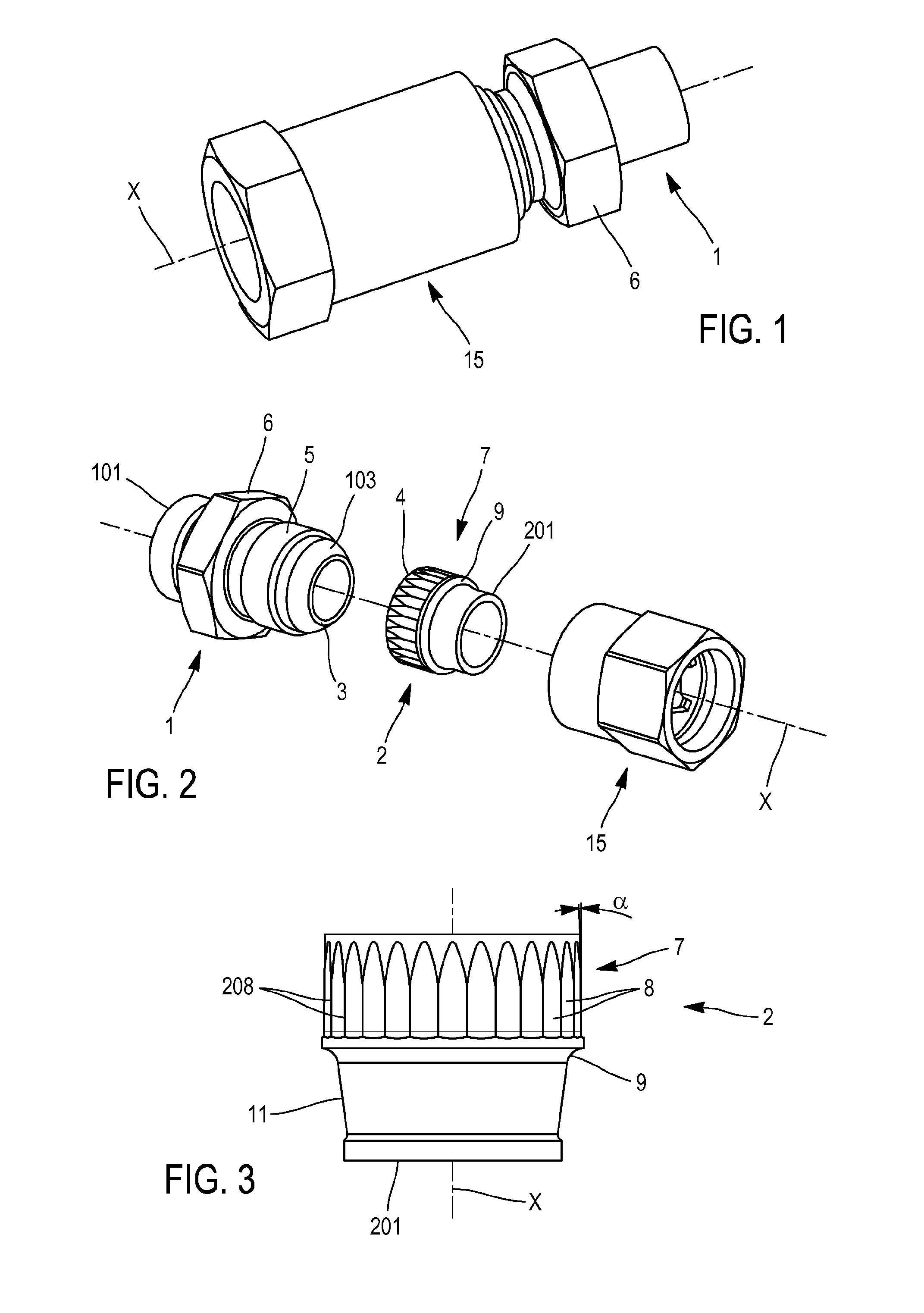
[0040]FIG. 1 is a perspective view of an embodiment of the locking device and of the connecting device according to the invention,

[0041]FIG. 2 is an exploded perspective view of the device of FIG. 1,

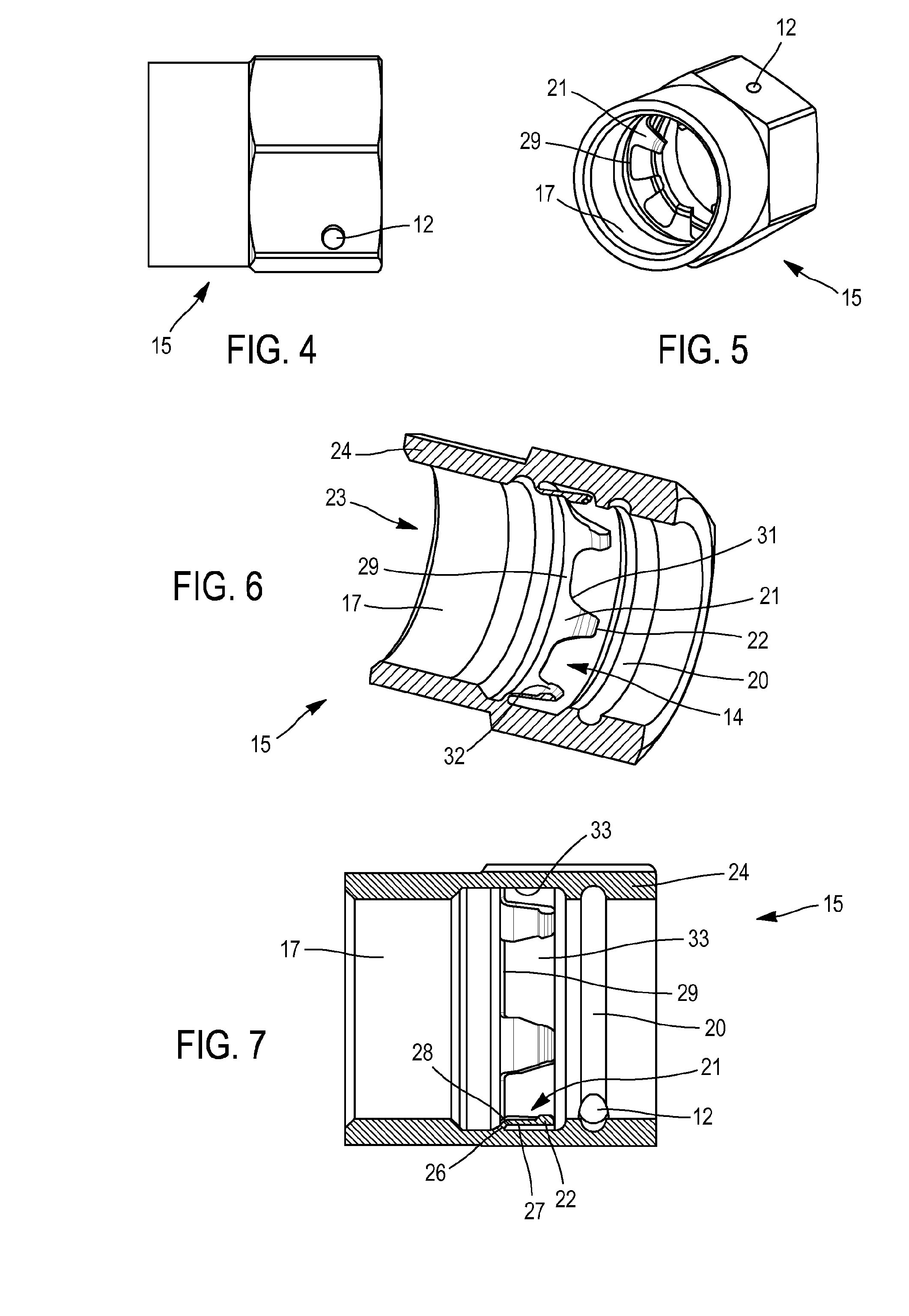
[0042]FIGS. 3 and 4 are elevation views of the second end-coupler and the nut, respectively,

[0043]FIG. 5 is a perspective view of the nut at an intermediate manufacturing stage,

[0044]FIGS. 6 and 7 are axial cross-section and perspective cross-section views of the nut, respectively,

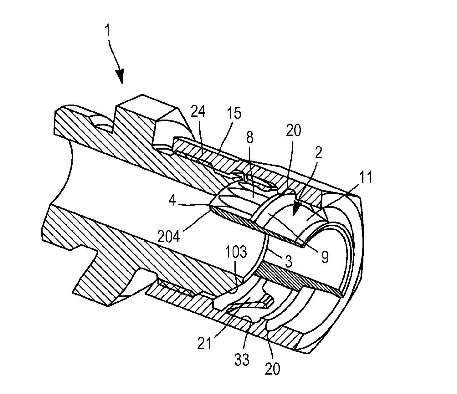
[0045]FIG. 8 is an axial perspective cross-section view of the connecting device in the connected state,

[0046]FIG. 9 is an axial cross-section view of the device in the connected state, and

[0047]FIG. 10 is an axial perspective cross-section view showing a step of forming anti-rotation recesses on the second end-coupler.

[0048]Si...


PUM


Abstract

The device connects a first end-coupler with a second end-coupler, in particular of a piping. A nut is provided with a threaded bore in which the first end-coupler is screwed along a longitudinal axis. In a tightening position, the first end-coupler is in axial stress with a second end-coupler accommodated in the nut. Anti-rotation means are provided between the nut and at least one of the end-couplers to prevent relative rotation except when a torque exceeding a predetermined threshold is applied thereto. The anti-rotation means consist of at least one tab made in the material of the nut to lockingly interfere with substantially planar faces formed on the second end-coupler.

Description

FIELD OF THE INVENTION[0001]The invention relates to a safety connecting device, in particular between two piping end-couplers.[0002]The invention also relates to an end-coupler for such a device.[0003]The invention further relates to a method for manufacturing a nut intended to be part of the device.STATE OF PRIOR ART AND RELATED PROBLEMS[0004]The function of the connecting device is to provide for mechanical connection of a first end-coupler with a second end-coupler by means of a tightening nut, and to avoid the inopportune unscrewing between the elements, in particular in applications where the elements are subjected in operation to vibration or shaking.[0005]The invention is directed more particularly but without limitation to standardized end-couplers of pipings to be connected, one of the end-couplers having a nipple intended to be pressed into a corresponding flare of the other end-coupler, for example a nozzle, under the action of tightening a nut being captive of one of th...

Claims


Application Information

Patent Timeline
IPC IPC(8): F16L19/02F16L19/00B21K1/70
CPCF16L19/0231F16L19/005B21K1/70F16L19/00
Inventor MARC, DAMIENLE GOUILL, GILLESROULAND, JEAN-PHILIPPE
Owner JPB SYST
Learn More