A mold locking mechanism for blow molding equipment

A blow molding equipment and mold technology, applied in the field of mold locking mechanism, can solve the problems of reduced reliability of the mechanism, inability to eliminate, and inability to eliminate noise.

Active Publication Date: 2017-10-31
GUANGZHOU TECH LONG PACKAGING MACHINERY CO LTD
View PDF8 Cites 0 Cited by
  • Summary
  • Abstract
  • Description
  • Claims
  • Application Information

AI Technical Summary

Problems solved by technology

[0004] However, the disadvantages of this mold locking mechanism are: 1. When the mold locking pin 400 is inserted into the locking nostril 101 of the mold locking shaft assembly 100 under the force of the elastic force of the spring 800, the noise generated by the impact is relatively large and cannot be eliminated; When the left and right mold bases 500 and 600 are closed, the left mold base 500 and the clamping pin 400 will also generate noise due to impact, and this impact is to make the clamping pin 400 withdraw from the lock nose 101 to ensure that the clamping shaft assembly 100 is lowered to achieve clamping , so the noise cannot be eliminated; 3. If the spring 800 is fatigued due to quality problems or too many cycles, the locking pin 400 will not be able to be inserted and withdrawn from the lock nose hole 101 normally, and the reliability of the mechanism will be reduced.

Method used


Image

  • A mold locking mechanism for blow molding equipment
  • A mold locking mechanism for blow molding equipment
  • A mold locking mechanism for blow molding equipment

Examples


Embodiment Construction

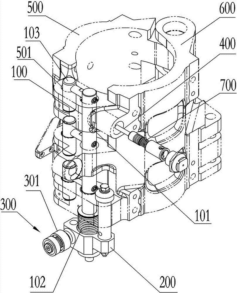
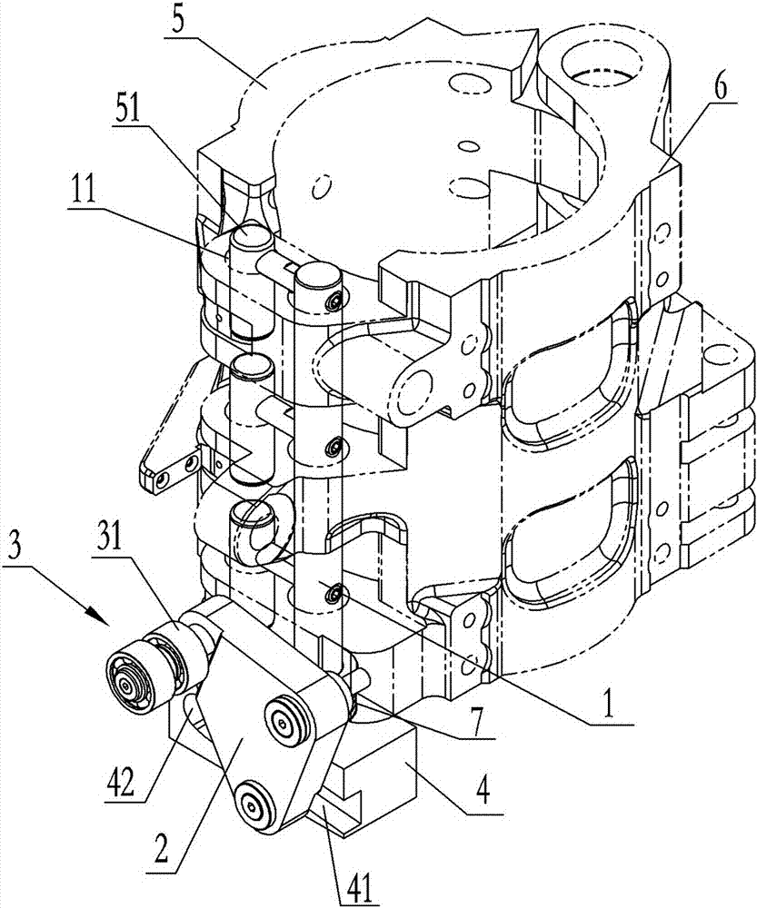
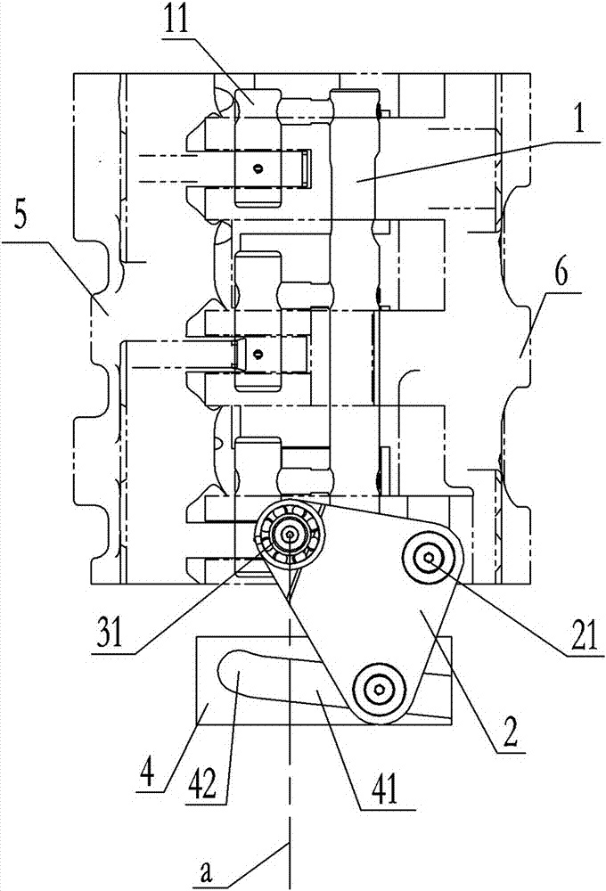
[0012] Such as Figures 2 to 4 As shown, a mold locking mechanism of blow molding equipment includes two mold frames 5, 6 installed on a rotating frame (not shown in the figure) and driven by a driving mechanism (not shown in the figure) to realize opening or closing , one of the mold frames 6 is equipped with a clamping shaft assembly 1 that can slide up and down and is hinged with a swing arm 2. The lower part of the locking shaft assembly 1 is fixed with a connecting block 4, and the lower part of the locking shaft assembly 1 is located at the bottom of the connecting block 4. The upper position is set with the booster top spring 7, the upper end of the booster top spring is against the mold frame 6, and the lower end is against the connecting block 4, exerting downward elastic force on the clamping shaft assembly 1, and the connecting block 4 and the swing arm 2 are opposite to each other. Sides are respectively provided with slideway 41 and toggle shaft 8 extending into s...


PUM


Abstract

The invention discloses a mold locking mechanism of blow molding equipment. The starting end of the slideway is located on one side of the vertical line of the hinge axis of the swing arm, and the tail end extends from the self-locking position, which is located at the hinge of the swing arm. On the other side of the vertical line of the shaft, the rollers of the roller assembly drive the swing arm to swing when rolling along the clamping guide rail to drive the toggle shaft to move relative to the slideway. When the toggle shaft moves from the beginning to the end of the slideway, the drive is connected The block and the mold locking shaft assembly rise, and when the toggle shaft moves into the self-locking position of the slideway, the latch pin has upwardly exited the socket, and self-locking is realized. The present invention does not need to be provided with locking nostrils and clamping pins that can be inserted into the locking nostrils as in the prior art, and will not produce strong impacts and loud noises as in the prior art, and at the same time, it will not Generally prone to unstable work, unreliable, and low service life.

Description

technical field [0001] The invention relates to blow molding equipment, in particular to a mold locking mechanism of blow molding equipment. Background technique [0002] The rotary frame of the blow molding equipment is equipped with multiple workstations with mold parts and mold clamping mechanisms. Open or close, so as to drive the mold on the mold base to open or close at the same time with the mold base, to ensure that the preform can be quickly sent into the cavity of the mold for blow molding into a plastic container, and to ensure that the finished plastic container can be quickly removed from the out of the mold cavity. [0003] Such as figure 1 Shown is the mold locking mechanism in the prior art, which uses a direct-acting structure to lift the mold locking shaft assembly to open or lock the left and right mold frames, including the mold locking shaft assembly 100 installed on the right mold frame 600 that can slide up and down. The lower part of the clamping s...

Claims


Application Information

Patent Timeline
Patent Type & Authority Patents(China)
IPC IPC(8): B29C49/56
Inventor 邹大群吴志刚刘青山盘荣锋王彦锋
Owner GUANGZHOU TECH LONG PACKAGING MACHINERY CO LTD
Why Eureka
Try Eureka