Automatic liquid stopping type intravenous infusion unit

A technology for intravenous infusion and hemostasis, which is applied in the direction of instruments, drug devices, hypodermic injection devices, etc. It can solve problems such as difficulty in detection and understanding by patients, low reliability of sealing, deformation of floats, etc., to enhance trust and facilitate rapid transformation And upgrade, promote the effect of harmony

Inactive Publication Date: 2017-09-15
严友希
View PDF10 Cites 0 Cited by
  • Summary
  • Abstract
  • Description
  • Claims
  • Application Information

AI Technical Summary

Problems solved by technology

However, this design has the following disadvantages: the first is that when the float is located at the lower end of the drip pot and cuts off the liquid outlet path of the drip pot, the liquid will stop automatically at this time, and the liquid medicine of tens of milliliters blocked in the infusion set below the float cannot continue to be injected into the human body. , resulting in a waste of liquid medicine
The second is to use the lower end of the float to block the liquid outlet of the drip pot. The lower end of the float must be precisely connected to the liquid outlet of the drip pot. The extrusion of the intravenous infusion set during transportation and other links will easily deform the drip pot and the float, resulting in low sealing reliability. , low security
The disadvantage of this design is that it is difficult for patients to perceive and understand this design, which leads to unnecessary tension for patients.

Method used


Image

  • Automatic liquid stopping type intravenous infusion unit
  • Automatic liquid stopping type intravenous infusion unit

Examples


Embodiment Construction

[0015] The present invention will be further described now in conjunction with accompanying drawing. These drawings are all simplified schematic diagrams, which only illustrate the basic structure of the present invention in a schematic manner, so they only show the configurations related to the present invention.

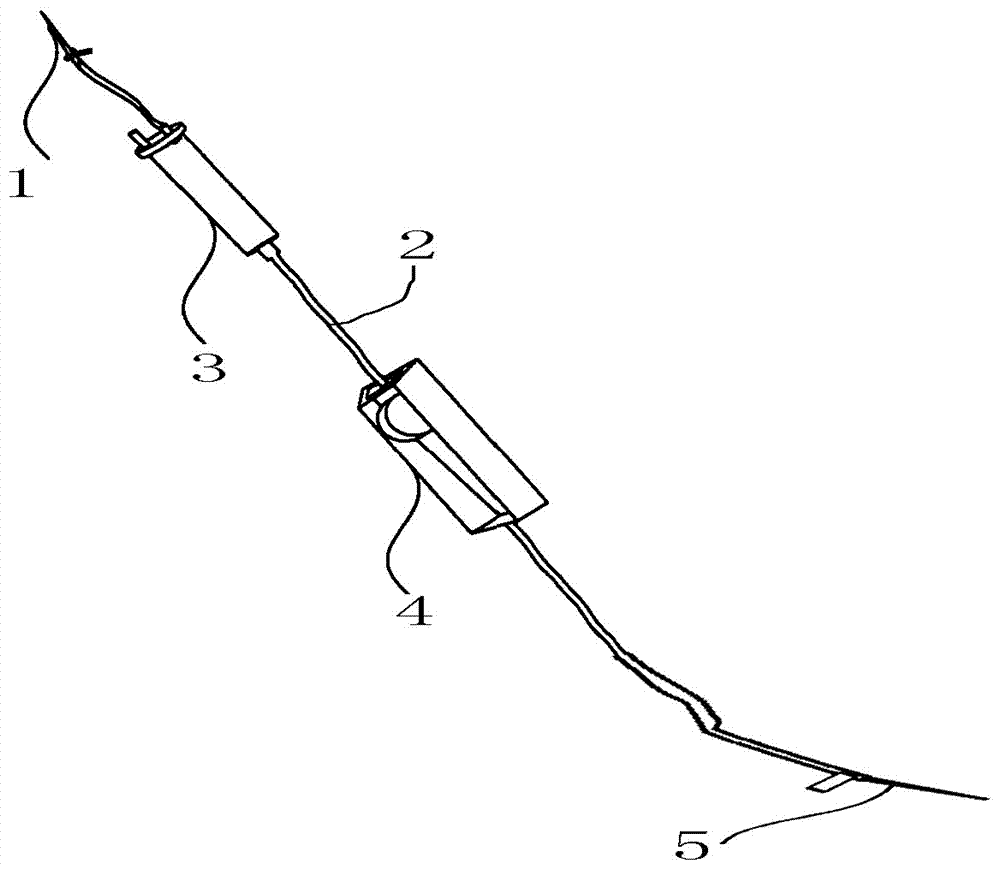
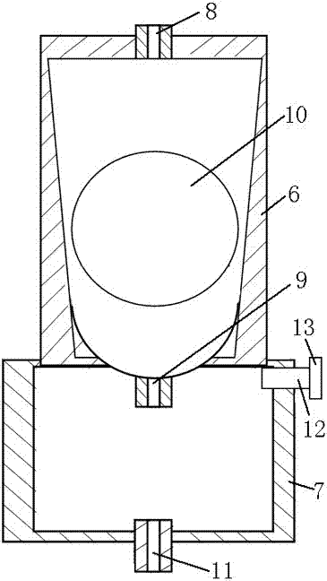
[0016] The infusion hose 2 connects the bottle stopper puncturer 1, the drip pot 3, the flow regulator 4, and the intravenous infusion needle 5 in sequence. The drip pot 3 is composed of the upper drip pot 6 and the lower drip pot 7, and the lower drip pot 7 is socketed on the The lower end of the upper drip pot 6; the cavity of the upper drip pot 6 is in the shape of an inverted cone; the upper end of the upper drip pot 6 is provided with a liquid inlet 8, and the cavity of the upper drip pot 6 is provided with a floating body 10, which is a spherical structure; A spherical structure with an upward opening is arranged between the upper drip pot 6 and the lower dri...


PUM


Abstract

The invention discloses an automatic liquid-stopping intravenous infusion device, which comprises a cork puncturer, an infusion hose, a drip pot, a flow regulator, and an intravenous infusion needle. The drip pot is composed of an upper drip pot and a lower drip pot, and the lower drip pot has a cover Connected to the lower end of the upper dripping pot; the cavity of the upper dripping pot is in the shape of an inverted cone; the upper end of the upper dripping pot is provided with a liquid inlet, and a floating body is arranged in the cavity of the upper dripping pot, and the floating body is a spherical structure; between the upper dripping pot and the lower There is a spherical structure with an upward opening between the dripping pots. The diameter of the spherical structure is equal to the length of the narrow opening at the lower end of the cavity. There is a liquid outlet at the bottom of the spherical structure; The upper end is provided with an air filter tube, and the outer end of the air filter tube is provided with a switch. The structure of this design is simple, which not only greatly improves the reliability of stopping the liquid, but also can manually control the liquid medicine placed in the infusion set to continue to be injected into the human body, which can effectively guarantee the therapeutic effect, help to enhance the trust of patients in nurses, and promote the development of nurses and nurses. harmonious.

Description

technical field [0001] The invention relates to an intravenous transfusion device, in particular to an automatic liquid-stopping intravenous transfusion device. Background technique [0002] Traditional intravenous infusion sets are generally composed of intravenous infusion needles, infusion hoses, liquid medicine filters, flow rate regulators, drip pots, cork puncturers, and air filters for intake pipes. If it is not timely, the medicine liquid will easily lead to blood backflow or even air input into the human body, which will affect the patient's health; at the same time, it will also increase the intensity of the nursing work of the medical staff, which will easily lead to doctor-patient disputes. With the continuous development of infusion technology and the increasing clinical requirements, people expect a better product that is safer and more effective. The automatic stop liquid infusion set is a new type of intravenous infusion set that replaces the traditional infu...

Claims


Application Information

Patent Timeline
IPC IPC(8): A61M5/14A61M5/40A61M5/168
CPCA61M5/14A61M5/16804A61M5/40A61M2205/3334
Inventor 严友希
Owner 严友希
Why Eureka
Try Eureka