Gear drive type ratchet wheel lifting mechanism

A lifting mechanism and transmission type technology, applied in the direction of lifting device, etc., can solve the problems of poor transmission reliability, easy damage and labor, and achieve the effect of high reliability and stable transmission

Inactive Publication Date: 2015-10-14
JIANGXI HONGDU AVIATION IND GRP
View PDF6 Cites 0 Cited by
  • Summary
  • Abstract
  • Description
  • Claims
  • Application Information

AI Technical Summary

Problems solved by technology

Due to the large distance between two adjacent teeth of the ratchet, the actual operation is more laborious, and the transmission reliability is poor and easy to be damaged

Method used


Image

  • Gear drive type ratchet wheel lifting mechanism
  • Gear drive type ratchet wheel lifting mechanism
  • Gear drive type ratchet wheel lifting mechanism

Examples


Embodiment Construction

[0018] The present invention will be further described below in conjunction with the accompanying drawings and specific embodiments. The following examples are only used to illustrate the present invention, and are not intended to limit the protection scope of the present invention.

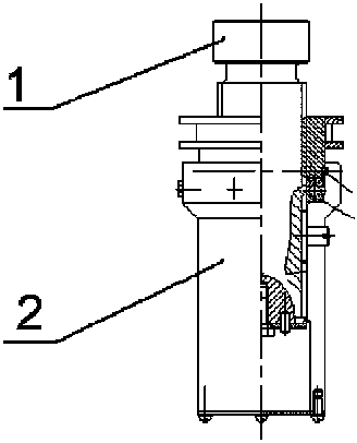
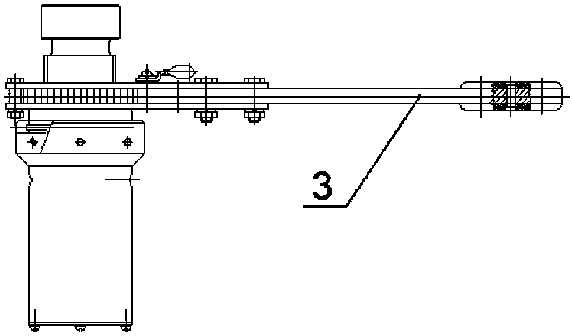
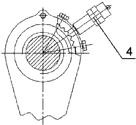
[0019] Figure 1a , Figure 1b and Figure 1c As shown, a gear-driven ratchet lifting mechanism of the present invention includes a ratchet wrench assembly 3, a screw shaft 1, a sleeve 2 and a brake 4, and the ratchet wrench assembly 3 and the brake 4 are installed on the sleeve 2 to drive the screw shaft 1 Do lifting movement, the screw shaft 1 is installed in the sleeve 2 and cooperates with the sleeve 2, the brake 4 brakes the ratchet wrench assembly 3, and the ratchet wrench assembly 3 lifts and adjusts the screw shaft 1, and the top of the screw shaft 1 is used for Support heavy objects.

[0020] Figure 2a , Figure 2b As shown, the ratchet wrench assembly 3 includes a ratchet 31, a st...


PUM


Abstract

The invention discloses a gear drive type ratchet wheel lifting mechanism which comprises a ratchet wheel wrench component, a screw shaft, a sleeve and a brake. The ratchet wheel wrench component and the brake are arranged on the sleeve. The screw shaft is driven to do lifting motion and is arranged in the sleeve and matched with the sleeve. The brake brakes the ratchet wheel wrench component. Lifting adjustment is carried out on the screw shaft through the ratchet wheel wrench component. The top end of the screw shaft is used for bearing weights. The gear drive type ratchet wheel lifting mechanism is composed of the ratchet wheel wrench component, the screw shaft, the sleeve and the brake; the brake is used for braking a ratchet; it is guaranteed that the ratchet is kept static when a check block moves along the ratchet; the ratchet wheel wrench component is in a gear drive type, transmission tends to be non-polar and is smooth and high in reliability; when a ratchet wheel wrench is operated to swing, the ratchet wheel wrench is more stable and saves more labor. The lifting mechanism is high in reliability, and no slipping phenomenon happens. When the lifting mechanism is operated manually, more time and labor are saved.

Description

technical field [0001] The invention relates to a lifting mechanism, in particular to a gear transmission ratchet lifting mechanism. Background technique [0002] The lifting mechanism of previous jacks or other similar products all adopts ratchet transmission. Due to the large distance between two adjacent teeth of the ratchet, it is relatively laborious to operate in practice, and the transmission reliability is poor and easy to be damaged. [0003] Therefore, it is necessary to provide a new technical solution to solve the above problems. Contents of the invention [0004] The technical problem to be solved by the present invention is to provide a gear-driven ratchet lifting mechanism. It saves time and effort when manually operating the lifting mechanism, and improves the reliability of the lifting mechanism. [0005] For solving the technical problem of the present invention, the technical scheme that the present invention adopts is: [0006] A gear-driven ratchet...

Claims


Application Information

Patent Timeline
Patent Type & Authority Applications(China)
IPC IPC(8): B66F3/14
CPCB66F3/14
Inventor 李新武罗云石林张红余孙春春熊志艳袁素娇邹志强杨龙军刘朝宏马威方源章伟罗敏芳张鹏
Owner JIANGXI HONGDU AVIATION IND GRP
Why Eureka
Try Eureka