

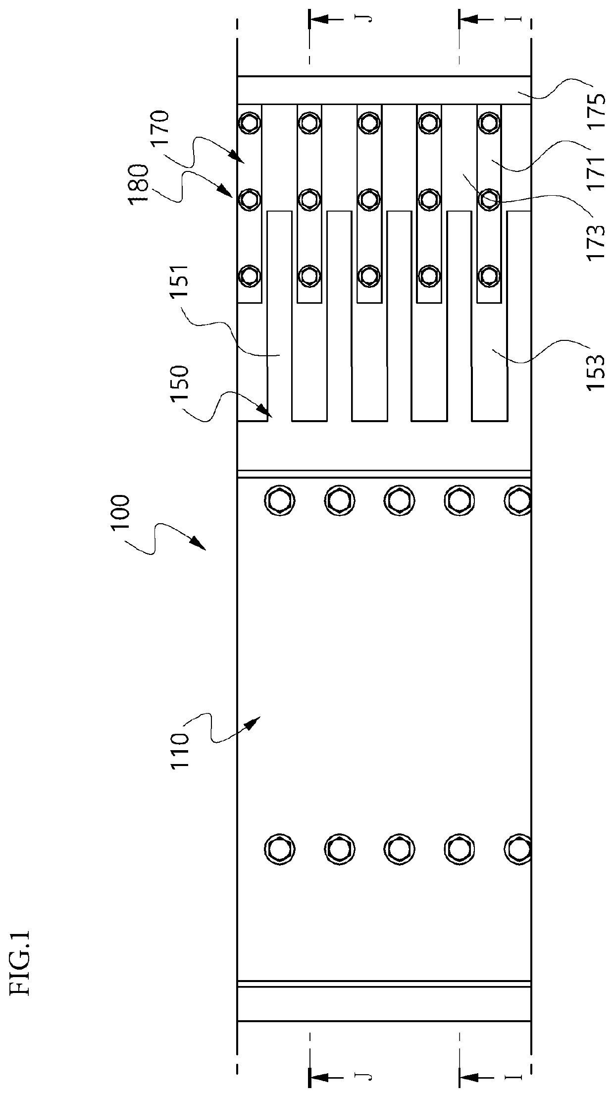
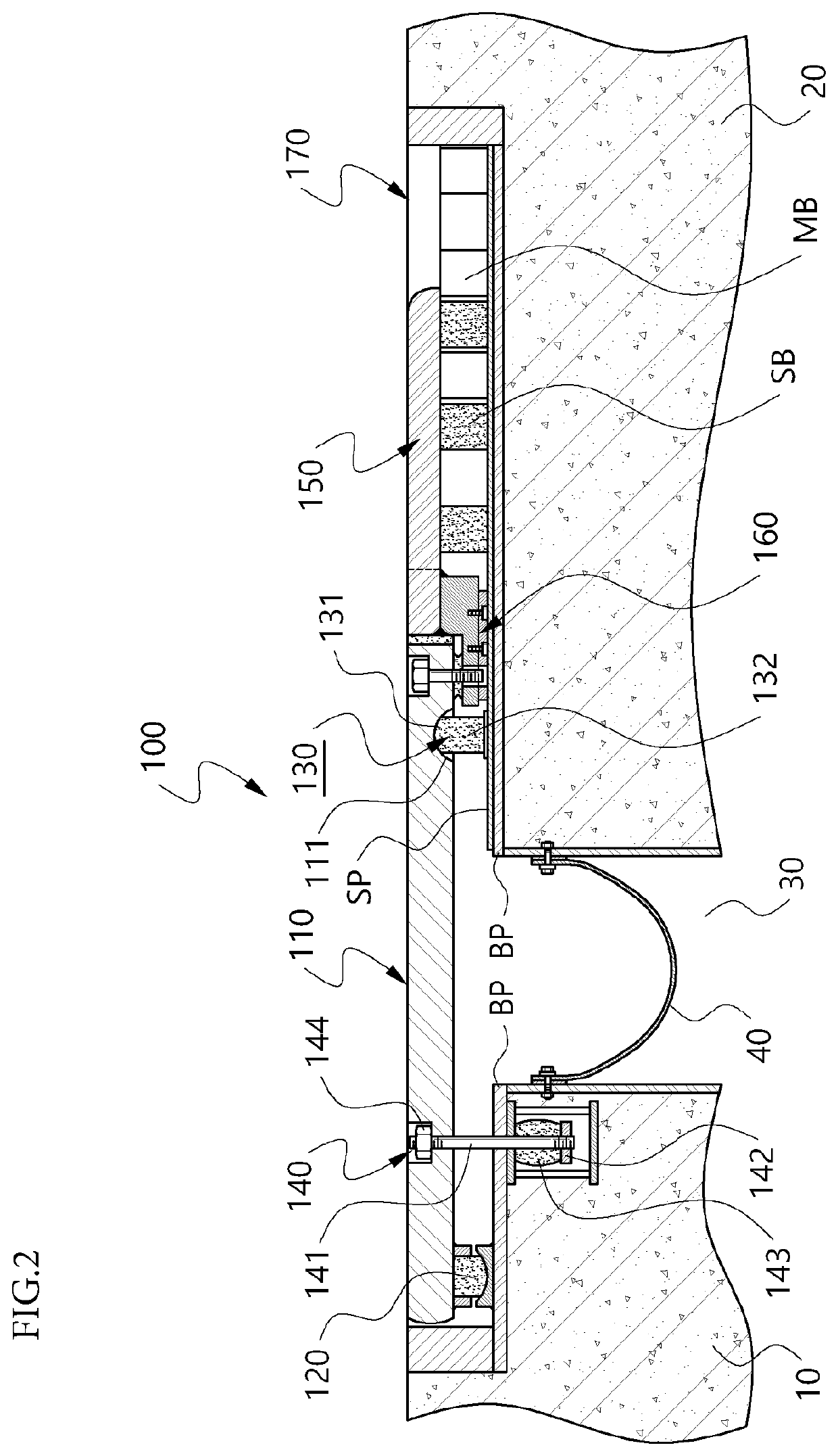
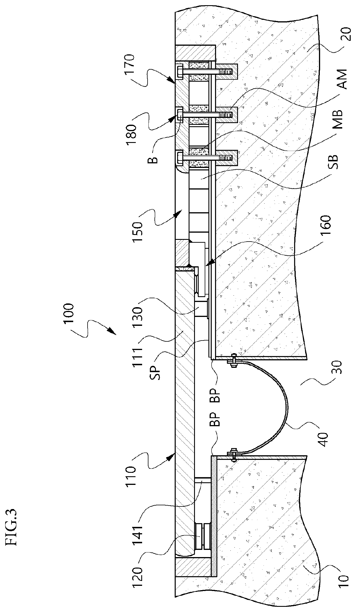
Finger joint with a bridging cover plate
- Summary
- Abstract
- Description
- Claims
- Application Information
AI Technical Summary
Benefits of technology
Problems solved by technology
Method used
Image

Examples
Embodiment Construction
Technical Problem
[0006]An object of the present invention is to provide a finger joint, which is capable of significantly reducing the thickness of an iron plate necessary for manufacturing the finger joint compared with conventional ones.
[0007]Another object of the present invention is to provide a finger joint, which is capable of significantly reducing the thickness of an iron plate necessary for manufacturing a finger joint, so that the finger joint is suitable for use in a medium-length bridge, a long bridge, or a super-long bridge, in which the amount of expansion and contraction is large.
[0008]Still another object of the present invention is to provide a finger joint, which is excellent in structural stability and provides good vehicle traveling properties compared with conventional finger joints.
[0009]Still another object of the present invention is to provide a finger joint, which is capable of preventing occurrence of a line contact portion between the finger joint and a s...
PUM
 Abstract
Description
Claims
Application Information