Eureka AIR delivers breakthrough ideas for toughest innovation challenges, trusted by R&D personnel around the world.

Occupant protection device

Active Publication Date: 2020-03-10
TOYOTA JIDOSHA KK
View PDF29 Cites 3 Cited by
  • Summary
  • Abstract
  • Description
  • Claims
  • Application Information

AI Technical Summary

Benefits of technology

[0009]According to the above configuration, in a case in which a vehicle side-on collision has been predicted by the side collision prediction section in a state in which the support face of the lumbar support section is not at the retreated position, the support face of the lumbar support section is displaced to the retreated position. The upper body of the seated occupant that was resting against the width direction intermediate portion of the seatback accordingly undergoes displacement toward the seatback rear side under its own weight, thereby enabling an overlap amount between the side support section and the seated occupant as viewed from the side of the vehicle to be increased. This thereby enables the seated occupant attempting to move in the vehicle width direction during a side-on collision to be stably supported by the side support sections as a result.
[0011]According to the above configuration, in a case in which a vehicle side-on collision has been predicted by the side collision prediction section in a state in which the supporting face of the lumbar support section is not at the retreated position, the pre-tensioner is actuated, and the seatbelt is taken up onto the spool so as to match the displacement of the support face of the lumbar support section toward the seatback rear side. The upper body of the seated occupant accordingly undergoes displacement toward the seatback rear side while being pushed against the width direction intermediate portion of the seatback by the seatbelt (shoulder belt portion). This thereby enables the overlap amount between the side support section and the seated occupant as viewed from the side of the vehicle to be increased even more stably, and also enables the restraint performance of the seated occupant to be further improved in the event of a side-on collision.
[0013]According to the above configuration, in a case in which a vehicle side-on collision has been predicted by the side collision prediction section in a state in which the bladder body disposed inside the side support section is not in the maximum inflation state, the gas supply mechanism is actuated and gas is supplied into the bladder body. The bladder body accordingly attains the maximum inflation state, such that the side support section protrudes out further toward the seatback front side. This thereby enables the seated occupant attempting to move in the vehicle width direction to be supported even at the locations where the side support section protrudes out further toward the seatback front side in the event of a side-on collision.
[0014]As described above, the occupant protection device of the present invention exhibits the excellent advantageous effect of enabling a seated occupant to be well-supported by the side support section in the event of a side-on collision, even when, due to user operation, the support face of the lumbar support section is not set at the retreated position.

Problems solved by technology

However, this related art is not a configuration in which a width direction intermediate portion of the seatback is provided with a lumbar support section that has a support face that supports the lumbar region of the seated occupant and is displaceable in the seatback front-rear direction, and is therefore not a configuration that gives consideration to the setting of a support face of the lumbar support section.

Method used


Image

  • Occupant protection device
  • Occupant protection device
  • Occupant protection device

Examples


first exemplary embodiment

[0022

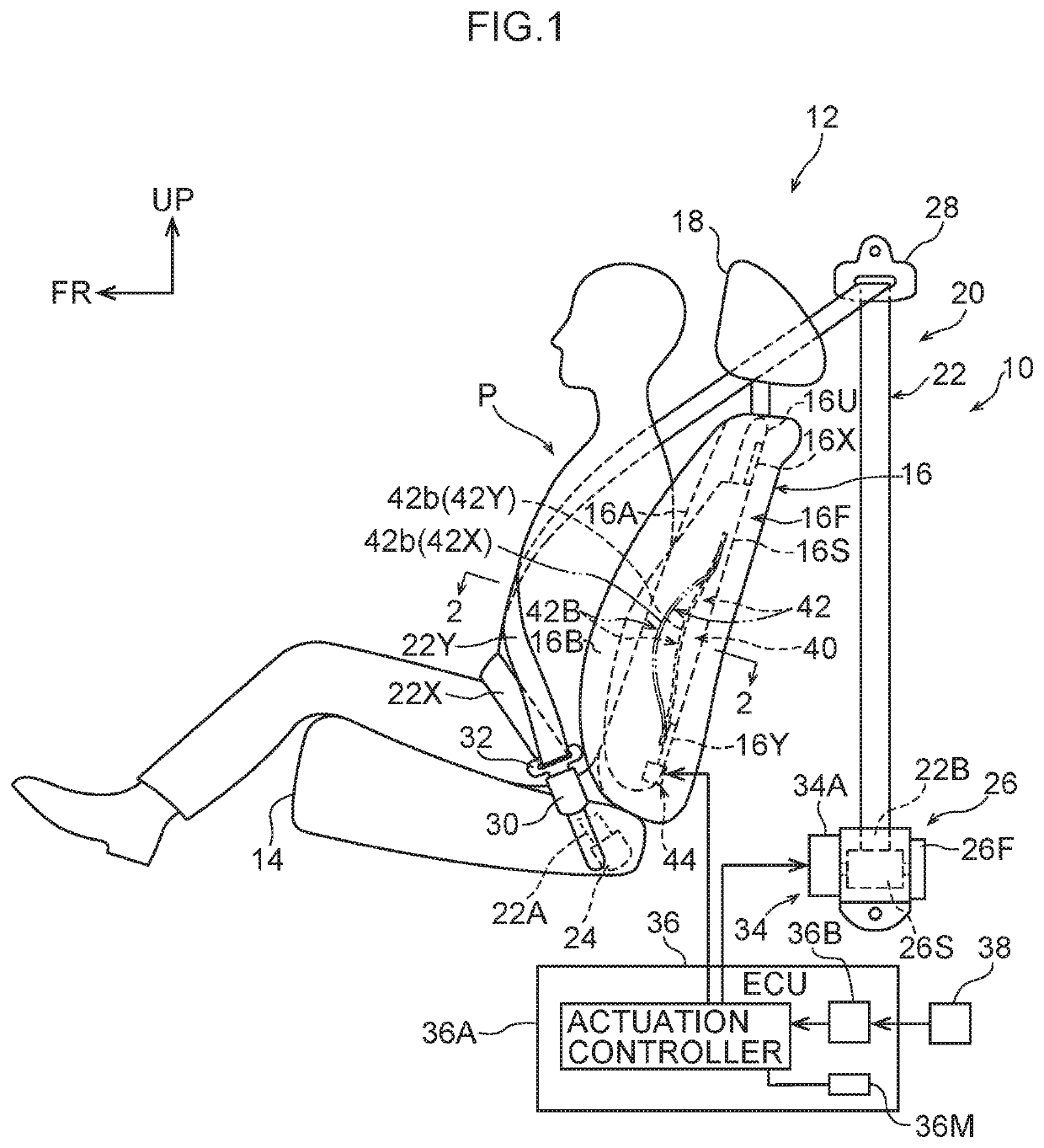
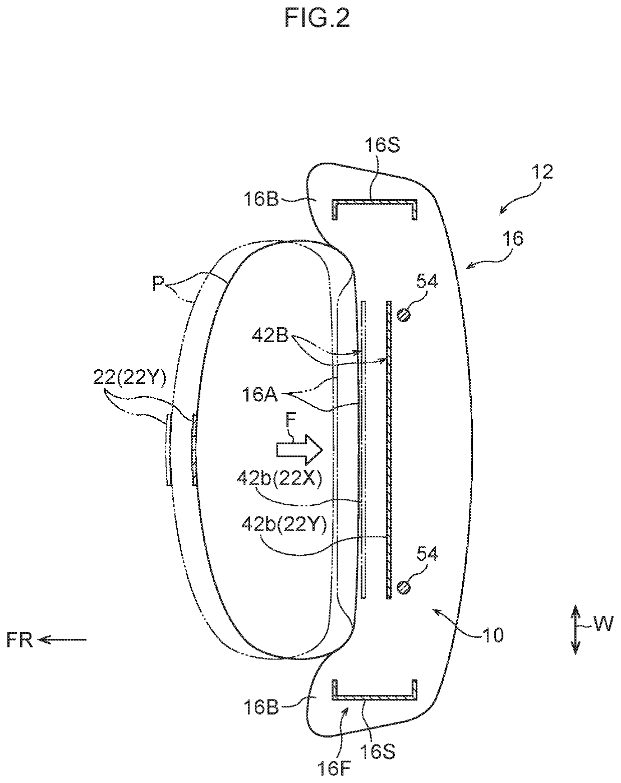
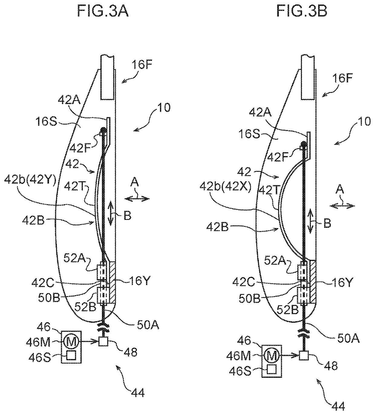
[0023]Explanation follows regarding an occupant protection device according to a first exemplary embodiment of the present invention, with reference to FIG. 1 to FIG. 3B. In the drawings, the arrow FR indicates the vehicle front side, the arrow UP indicates the vehicle upper side, and the arrow W indicates the vehicle width direction, as appropriate.

[0024]Vehicle Seat Schematic Configuration

[0025]FIG. 1 is a side view schematically illustrating a vehicle seat 12 applied with an occupant protection device 10 according to the present exemplary embodiment. As an example, the vehicle seat 12 illustrated in FIG. 1 configures a front driving seat disposed such that the seat width direction runs in the vehicle width direction, and disposed facing the vehicle front side. In the present exemplary embodiment, a World Side Impact Dummy P (WorldSID) is seated in the vehicle seat 12 in the place of an actual occupant. The seating posture is as currently specified in the Japanese and Europea...

second exemplary embodiment

[0058

[0059]Next, explanation follows regarding an occupant protection device 60 according to a second exemplary embodiment of the present invention, with reference to FIG. 4 and FIG. 5. Note that the second exemplary embodiment has substantially the same configuration as the first exemplary embodiment with the exception of the points described below. Accordingly, in the second exemplary embodiment, configuration sections that are substantially the same as in the first exemplary embodiment are allocated the same reference numerals, and explanation thereof is omitted.

[0060]FIG. 4 is a schematic side view illustrating the occupant protection device 60 according to the present exemplary embodiment, together with part of a vehicle seat 12. For ease of viewing, in FIG. 4, out of the internal configuration of a width direction intermediate portion of the backrest section 16A, configuration sections that are relevant portions of the present exemplary embodiment are illustrated by solid line...


PUM


Abstract

An occupant protection device including: a side support section; a lumbar support section that is provided to the width direction intermediate portion of the seatback, and that has a support face displaceable between an advanced position pressing the lumbar region and a retreated position further to a seatback rear side than the advanced position; a displacement mechanism that displaces the support face of the lumbar support section between the advanced position and the retreated position; a side collision prediction section; an actuation controller that, in a case in which a vehicle side-on collision has been predicted by the side collision prediction section in a state in which the support face of the lumbar support section is not at the retreated position, controls the displacement mechanism so as to displace the support face of the lumbar support section to the retreated position.

Description

CROSS-REFERENCE TO RELATED APPLICATION[0001]This application is based on and claims priority under 35 USC 119 from Japanese Patent Application No. 2015-135579 filed on Jul. 6, 2015, the disclosure of which is incorporated by reference herein.BACKGROUND[0002]Technical Field[0003]The present invention relates to an occupant protection device.[0004]Related Art[0005]Structures and devices are known for protecting an occupant seated in a vehicle seat in the event of a side collision to the vehicle (Japanese Patent Application Laid-Open (JP-A) Nos. 2006-110221, 2008-207764, 2000-125988). For example, JP-A No. 2006-110221 describes a structure in which portions on both width direction sides of a seatback configure side support sections that protrude out further toward the seat front side than a width direction intermediate portion of the seatback. In this structure, a seated occupant is supported by the side support sections in the event of a side-on collision.[0006]The related art describ...

Claims


Application Information

Patent Timeline
Patent Type & Authority Patents(United States)
IPC IPC(8): B60N2/66B60N2/90B60R16/02B60N2/42B60R21/015B60N2/427
CPCB60N2/914B60N2/4235B60N2/99B60N2/6671B60N2/4279B60R16/02B60N2/66B60N2/665B60N2/6673B60R21/015
Inventor OHNO, MITSUYOSHI
Owner TOYOTA JIDOSHA KK
Why Eureka
Eureka Blog
Learn More