Lower pair arc stop-block overrunning clutch
a technology of stop-block and arc stop block, which is applied in the field of lower-pair cambered surface stop-block type over-running clutch, and can solve the problems of significant reduction of torque withstand performance of the over-running clutch, reducing the working life of the wedge, and wedging performan
- Summary
- Abstract
- Description
- Claims
- Application Information
AI Technical Summary
Benefits of technology
Problems solved by technology
Method used
Image
Examples
embodiment 1
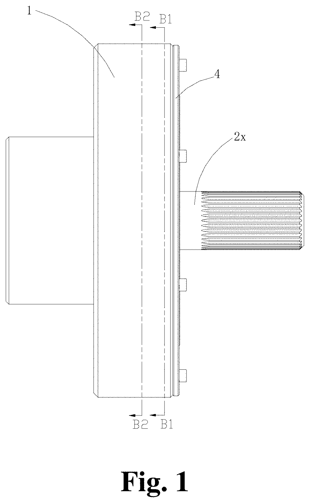
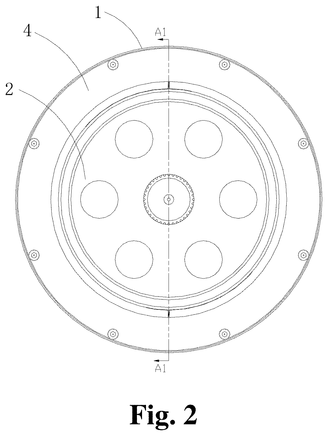
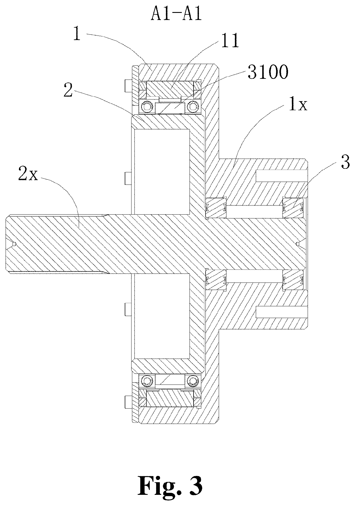
[0075]With reference to FIG. 1-3, the overrunning clutch of the present invention comprises an outer rotating element 1, an inner rotating element 2 and a clutch cover plate 4, wherein the outer rotating element 1 includes a shaft sleeve 1x and the inner rotating element 2 includes a shaft 2x; one end of the shaft 2x is fixed with a bearing 3 and the outer surface of the bearing 3 snaps into the shaft sleeve 1x so that the inner rotating element 2 can rotate more smoothly relative to the outer rotating element 1. When the inner rotating element 2 is mounted to the clutch cover plate 4 on the rear cover in the outer rotating element 1, the axial clearance of the structure in the outer rotating element 1 during rotation can be limited.
[0076]The outer rotating element 1 and inner rotating element 2 can be connected to an external transmission mechanism respectively by the shaft sleeve 1x and shaft 2x for application onto various occasions of toque transmission. When the inner rotating ...
embodiment 2
[0110]As shown in FIG. 12, different from Embodiment 1, the first lapping part and second lapping part at the end surfaces of the head and tail of each friction block are another structures different from Embodiment 1, specifically, both the first lapping part and second lapping part are configured to be an anti-hook structure extending from the end surfaces of friction blocks and folding outward while forming a first insert hole 100a at the first lapping part and a notch 100c at the second lapping part; during assembly, the first lapping part is inserted in to the notch 100c of the second lapping part, then the synchronized push-block assembly 50 is inserted into the first insert hole 100a and the notch 100c to keep the synchronized push-block assembly 50 snap between the two hook bodies. The first propeller assembly 30 pushed the push arm 51 to urge the block body 52 and rolling needles 53 to press the second and first lapping part respectively for keeping the two close to each ot...
embodiment 3
[0111]As shown in FIG. 13-19, the difference between above embodiment and the present embodiment mainly lies in the arrangement of the arc wedge surface 10S and cambered-surface stop surface 10a of the friction block assembly 10. The inner arc surface of the present embodiment is the arc wedge surface 10S and the outer surface is the cambered-surface stop surface 10a. The friction block assembly 10 is arranged between the first rotating ring 1a and the second rotating ring 2a, and the first elastic element 40′ is a tension spring with both ends fixed on the end surfaces of two adjacent friction blocks respectively for drawing the two adjacent friction blocks, specifically, the end surface of each friction block is provided with a through hole (not shown) for accommodating the tension spring and a fixed column (not shown) is provided in the through hole for the free end of the tension spring to hook; when in natural state, the tension spring draws two adjacent friction blocks and com...
PUM
 Abstract
Description
Claims
Application Information
 - R&D
- Intellectual Property
- Life Sciences
- Materials
- Tech Scout
- Unparalleled Data Quality
- Higher Quality Content
- 60% Fewer Hallucinations
Browse by: Latest US Patents, China's latest patents, Technical Efficacy Thesaurus, Application Domain, Technology Topic, Popular Technical Reports.
© 2025 PatSnap. All rights reserved.Legal|Privacy policy|Modern Slavery Act Transparency Statement|Sitemap|About US| Contact US: help@patsnap.com


