Control system and method for reciprocating compressors

a technology of control system and compressor, which is applied in the direction of pump control, pump parameter, piston pump, etc., can solve the problems of difficult design of suspension spring, difficult to control the vibration level of the suspension spring, and difficulty in reducing the rigidity of the spring. , to achieve the effect of minimizing the vibration level and reducing the rigidity of the spring

Active Publication Date: 2020-03-17
EMBRACO IND DE COMPRESSORES E SOLUCOES EM REFRIGERACAO LTDA
View PDF18 Cites 1 Cited by
  • Summary
  • Abstract
  • Description
  • Claims
  • Application Information

AI Technical Summary

Benefits of technology

[0010]Therefore, it is a first objective of this invention to provide a system and a method for reducing the rigidity of the springs of the suspension system, thus minimizing the vibration level during normal operation.
[0011]It is another objective of this invention to provide a system and a method that are capable of reducing the demand for robustness of the suspension system, maintaining the level of reliability and useful life of the springs, by preventing breakage thereof.
[0012]A further objective of this invention is to provide a system and a method that are capable of enabling the compressor to operate in conditions of high difference in pressure, under which it can be turned off without undesired impacts and noises being generated.BRIEF DESCRIPTION OF THE INVENTION

Problems solved by technology

The impulse is caused by the abrupt stopping of the axle or by the turning movement in an opposite direction at the last turn of the axle because the piston is not capable of overcoming the pressure.
Thus, the gas is compressed and uncompressed in an alternating movement, which may cause problems to the reciprocating compressor.
On the other hand, the springs should not be designed to be excessively soft to the point of allowing a long displacement of the assembly during this stopping impulse, since this may cause shocks at the mechanical stops, raising noises.
Besides, factors linked to the pressure condition and to the assembly mass make it difficult to design the suspension springs, and the more one wants to attenuate the normal-operation vibration the higher this project will be, especially in operation at low rotations.
Because of this, one encounters even more severe contour conditions, which are difficult to be met.
In deigns where there are severe pressure conditions, optimization of the assembly weight and the need to reduce considerably the vibration level in low-rotation operation, the solution to the spring design may not meet all the desired conditions.

Method used


Image

  • Control system and method for reciprocating compressors
  • Control system and method for reciprocating compressors
  • Control system and method for reciprocating compressors

Examples


Embodiment Construction

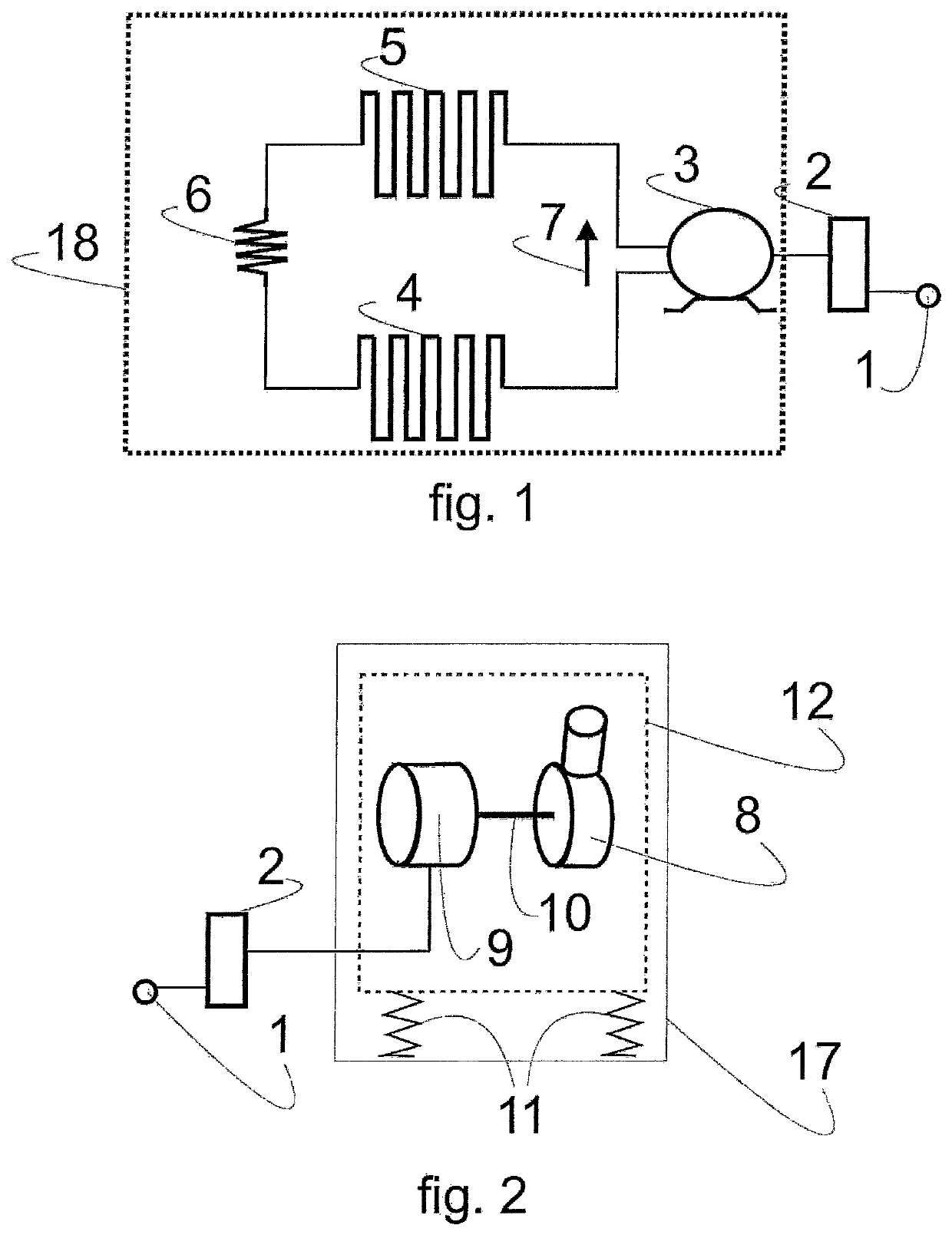
[0025]As represented in FIG. 1, a cooling system comprises a reciprocating compressor 3, which is fed by an electric power network 1 and has an electronic controller 2 capable of controlling the operation of a reciprocating compressor 3. The reciprocating compressor 3 drives a cooling gas in a gas-circulation closed circuit 18, creating a cooling-gas flow 78 inside this circuit, directing the gas to a condenser 5. After the condenser 5, the cooling gas goes though a flow-cooling device 6, which may be, for instance, a cappillary tube. Then, the gas is led to an evaporator 4 and later returns to the reciprocating compressor 3, restarting the gas-circulation circuit.

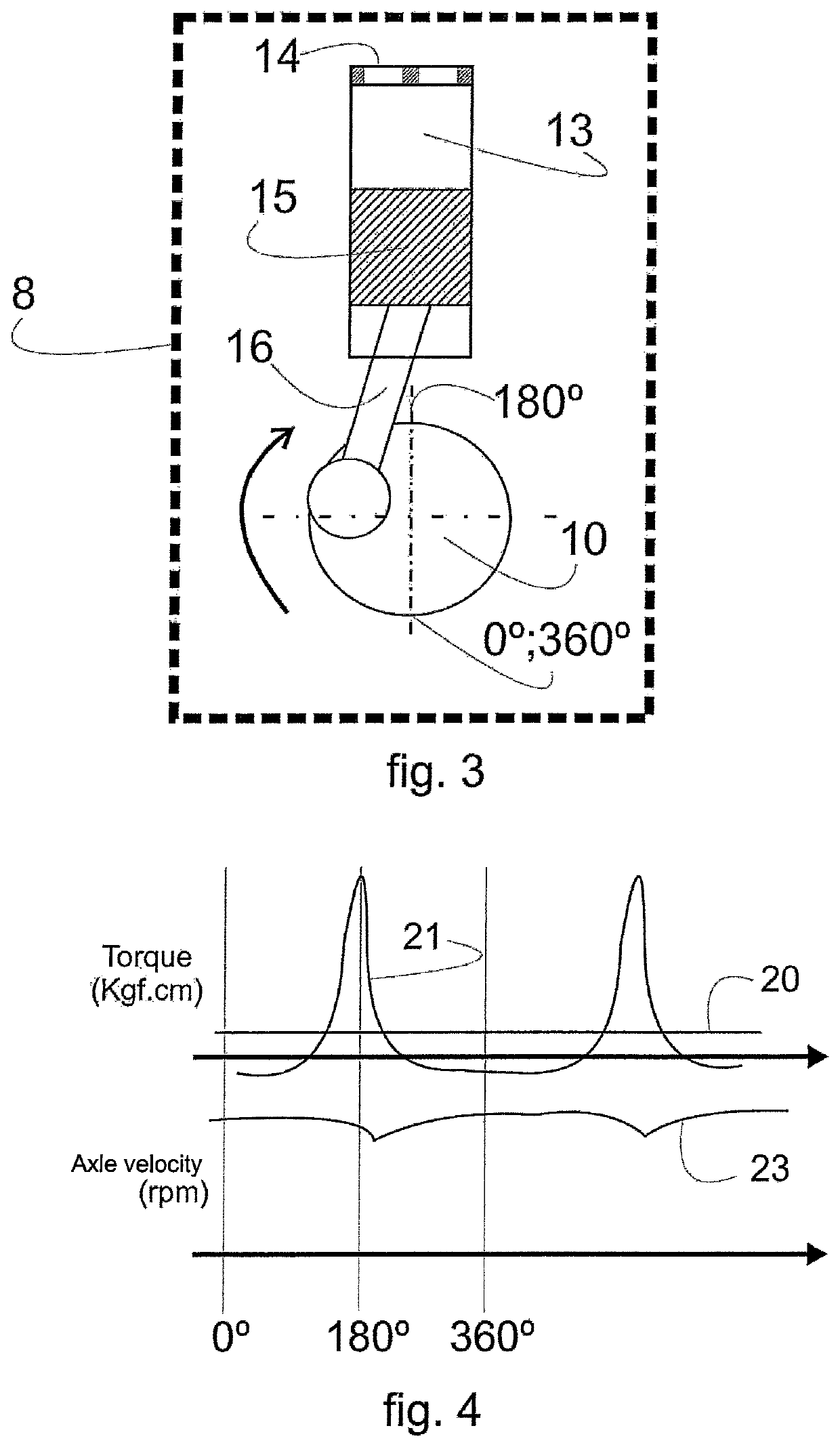
[0026]FIG. 2 illustrates a focus in subsystems inside the reciprocating compressor, the reciprocating compressor 3 being formed by a housing 17, suspension springs 11 that are responsible for damping the mechanical vibration generated by the movement of a mechanical assembly 12, formed by the motor 9 and the compression me...


PUM


Abstract

A control system for hermetic cooling compressor includes a reciprocating compressor (3) and an electronic control (2) for the reciprocating compressor (3). The electronic control (2) is configured for, after commanding the turning off of the reciprocating compressor (3), detecting whether the turn velocity (23) of the turning axle (10) is below a predefined velocity level, and then applying a braking torque (36) that causes deceleration of the turning axle (10) before completing the next turn of the turning axle (10), in case the turn velocity (23) detected is below the velocity level (34).

Description

[0001]The present invention relates to a system and a method that enable one to control the stopping (braking) behavior of a reciprocating compressor.DESCRIPTION OF THE PRIOR ART[0002]Hermitic compressor of reciprocating type comprise rod-crank-and-piston type with reciprocating movement and are widely used in the cooling-equipment, household and commercial industry.[0003]Reciprocating compressors may be of the fixed-capacity type, wherein the control of two fixed-velocity states (ON / OFF) is carried out upon turning on the compressor at a maximum temperature and turning off the compressor at a minimum temperature, or varying-capacity compressors, wherein the control is carried out by some electromechanical device or electronic circuit, capable of responding to a programming dependent upon variables to be controlled on the cooling equipment, as for instance the inner temperature of the compartments, wherein the compressor acts in reciprocating operation cycles at varying velocities a...

Claims


Application Information

Patent Timeline
Patent Type & Authority Patents(United States)
IPC IPC(8): F04B49/06F04B49/02F04B49/20F04B49/10F04B35/04
CPCF04B49/103F04B49/20F04B49/02F04B49/065F04B49/06F04B35/04F04B2201/0209F04B2201/127F04B2201/0201F04B2201/1201F04B2201/0802F05B2210/12Y10S415/00Y10S417/00
Inventor SCHWARZ, MARCOS GUILHERMENAZARIO, FILIPE GUOLO
Owner EMBRACO IND DE COMPRESSORES E SOLUCOES EM REFRIGERACAO LTDA
Why Eureka
Try Eureka