Carbody of railcar

a railcar and car body technology, applied in the direction of railway roofs, railway bodies, underframes, etc., can solve the problem that the appearance cannot be kept, and achieve the effect of obtaining the strength of the carbody and stably determining the vertical distan

Active Publication Date: 2020-03-24
KAWASAKI RAILCAR MFG CO LTD
View PDF8 Cites 0 Cited by
  • Summary
  • Abstract
  • Description
  • Claims
  • Application Information

AI Technical Summary

Benefits of technology

[0009]The present invention can provide a carbody of a railcar, the carbody being capable of stably determining a vertical distance between a roof bodyshell and a support target member without requiring work skills, and obtaining strength of the carbody.

Problems solved by technology

However, regarding the interior materials, even a small level difference is conspicuous, so that the appearances thereof cannot be kept.

Method used


Image

  • Carbody of railcar
  • Carbody of railcar
  • Carbody of railcar

Examples


embodiment 1

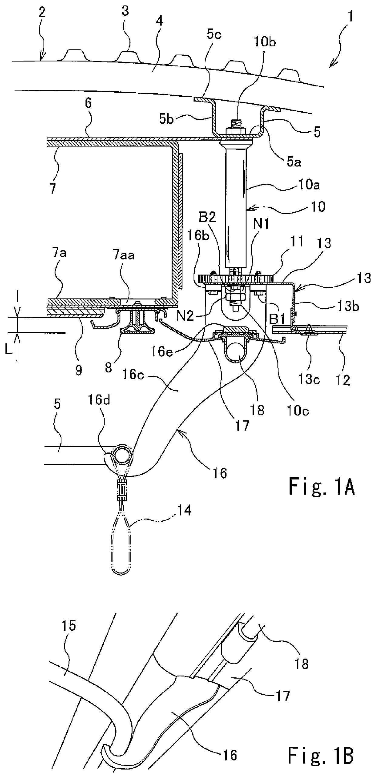
[0018]FIG. 1A is a major component sectional view showing a carbody 1 of a railcar according to Embodiment 1. FIG. 1B is an enlarged perspective view showing a part of the carbody 1 of FIG. 1A when viewed from below. As shown in FIGS. 1A and 1B, the carbody 1 of the railcar of the present embodiment includes a roof bodyshell 2. The roof bodyshell 2 includes a circular-arc corrugated plate 3 and a plurality of carlines 4. The corrugated plate 3 is convex upward when viewed from a railcar longitudinal direction (hereinafter may also be referred to as a rail direction or a forward / rearward direction). The plurality of carlines 4 are fixed to a lower surface of the corrugated plate 3, extends in a railcar width direction (hereinafter may also be referred to as a sleeper direction or a crosswise direction), and are arranged at intervals in the railcar longitudinal direction. A first reinforcing member 5 extending in the railcar longitudinal direction is fixed to lower surfaces of the car...

embodiment 2

[0033]FIG. 5 is a major component sectional view showing a carbody 101 of the railcar according to Embodiment 2. FIG. 6 is a plan view showing major components of the carbody 101 shown in FIG. 5. As shown in FIGS. 5 and 6, a receiving tray member 120 is fixed to the roof bodyshell 2. The receiving tray member 120 includes: a recess 120a that is open upward; and a flange portion 120b horizontally projecting from an upper end edge of the recess 120a. The recess 120a is rectangular in plan view. A rectangular nut N3 (rotating body) is accommodated in the recess 120a. The nut N3 has such a size as to interfere with side surfaces of the recess 120a and therefore be not rotatable by a predetermined angle or more. A hole 120aa that is smaller than the nut N3 is formed at a bottom wall portion of the recess 120a, so that the nut N3 does not fall off.

[0034]A supporting rod 110 having an axis extending in the vertical direction is inserted through the hole 120aa of the receiving tray member 1...

embodiment 3

[0040]FIG. 7 is a major component sectional view showing a carbody 201 of a railcar according to Embodiment 3. As shown in FIG. 7, the first reinforcing member 5 extending in the railcar longitudinal direction is fixed to the lower surface of the roof bodyshell 2, and a supporting rod 210 having an axis extending in the vertical direction is fixed to the first reinforcing member 5. The supporting rod 210 includes: a columnar rod main body portion 210a; a flange portion 210b projecting from an upper end of the rod main body portion 210a in the horizontal direction; and a lower end portion 210c provided at a lower side of the rod main body portion 210a. The lower end portion 210c is an external thread portion that is smaller in diameter than the rod main body portion 210a and projecting downward from the rod main body portion 210a.

[0041]The flange portion 210b of the supporting rod 210 is fixed to the first reinforcing member 5 by fastening members B3 (for example, bolts). The first ...


PUM


Abstract

A carbody of a railcar includes: a roof bodyshell; a supporting body provided under the roof bodyshell, the supporting body being attached to the roof bodyshell in a state of being positioned in the vertical direction; a rotating body which is threadedly engaged with the supporting body and rotates relative to the supporting body about an axis extending in a vertical direction to be displaced relative to the supporting body in the vertical direction; and a support target member supported by the roof bodyshell through the supporting body and the rotating body, the support target member being attached to the rotating body in a state of being positioned in the vertical direction, a vertical distance between the roof bodyshell and the support target member being adjustable by displacement of the rotating body relative to the supporting body.

Description

TECHNICAL FIELD[0001]The present invention relates to a carbody of a railcar.BACKGROUND ART[0002]In a carbody of a railcar, a passenger room where passengers stay is formed by attaching interior materials to a structure produced by joining metals to one another by welding. The structure is produced while giving priority to strength and the like for the purpose of withstanding loads generated by movements, braking, and the like of the railcar. On the other hand, since the interior materials are seen by the passengers, appearances thereof need to be kept. Since the structure is assembled by welding, manufacturing tolerance is set to be large. However, regarding the interior materials, even a small level difference is conspicuous, so that the appearances thereof cannot be kept. Therefore, liners are stacked on and adhere to an attachment surface of the structure, the interior materials being attached to the attachment surface, and with this, the attachment positions of the interior mat...

Claims


Application Information

Patent Timeline
Patent Type & Authority Patents(United States)
IPC IPC(8): B61D17/04B61D17/12B61D37/00B61D17/18B61F5/18B61F1/14
CPCB61D17/045B61D17/048B61F5/18B61D17/18B61D37/00B61D17/12B61F1/14
Inventor KATO, EIICHIGOTO, TSUNETOSHIMIURA, SHINICHITSUNODA, KOUICHISUGA, TAIMEIUEHARA, RYO
Owner KAWASAKI RAILCAR MFG CO LTD
Why Eureka
Try Eureka