Phase locked loop circuit, method of detecting lock, and system having the circuit

a technology of phase locking loop circuit and lock, which is applied in the direction of electrical equipment, pulse automatic control, etc., can solve the problems of high probability of pll circuit malfunction and system instability

Active Publication Date: 2011-09-22
SAMSUNG ELECTRONICS CO LTD
View PDF16 Cites 15 Cited by
  • Summary
  • Abstract
  • Description
  • Claims
  • Application Information

AI Technical Summary

Benefits of technology

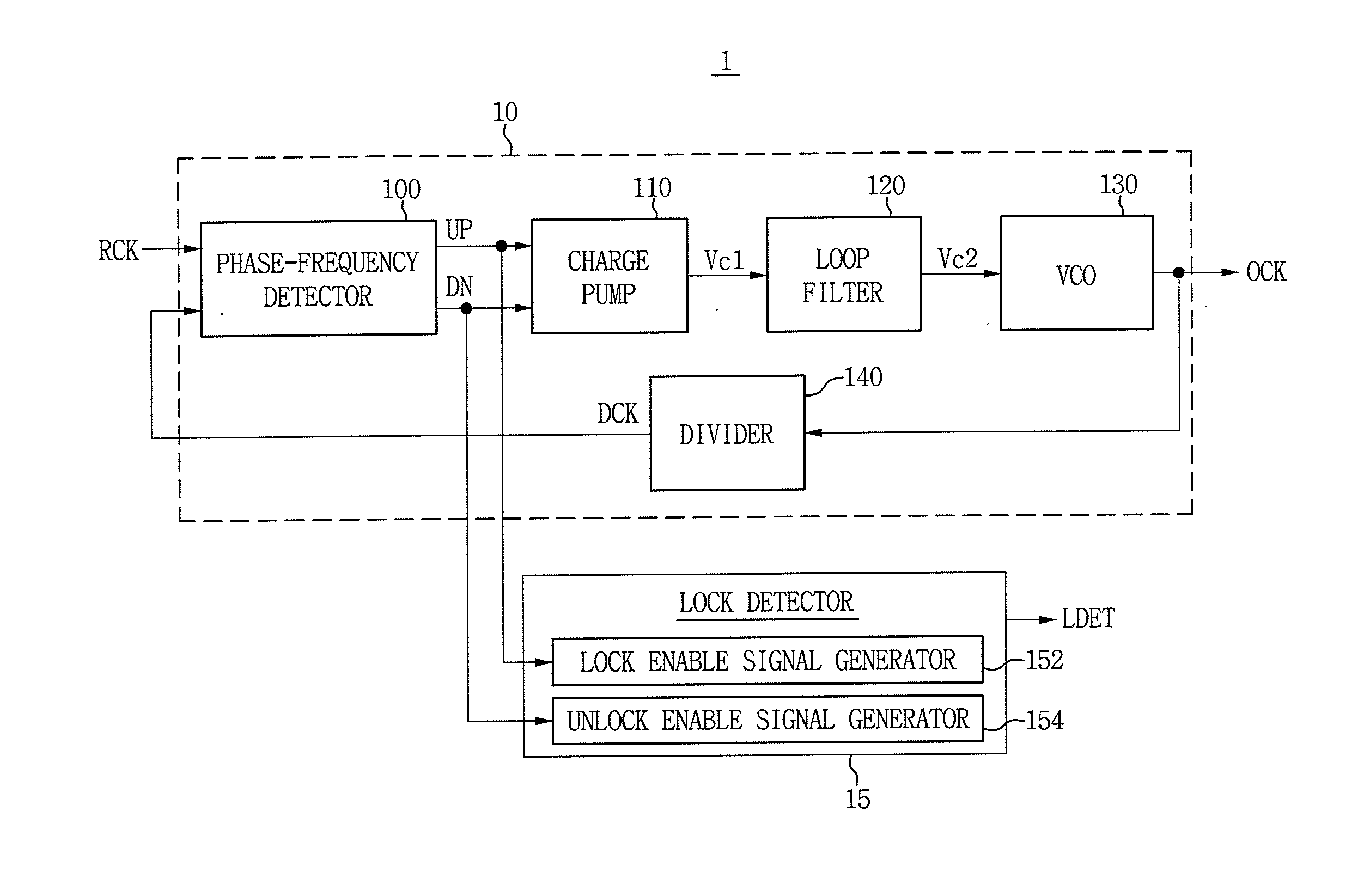
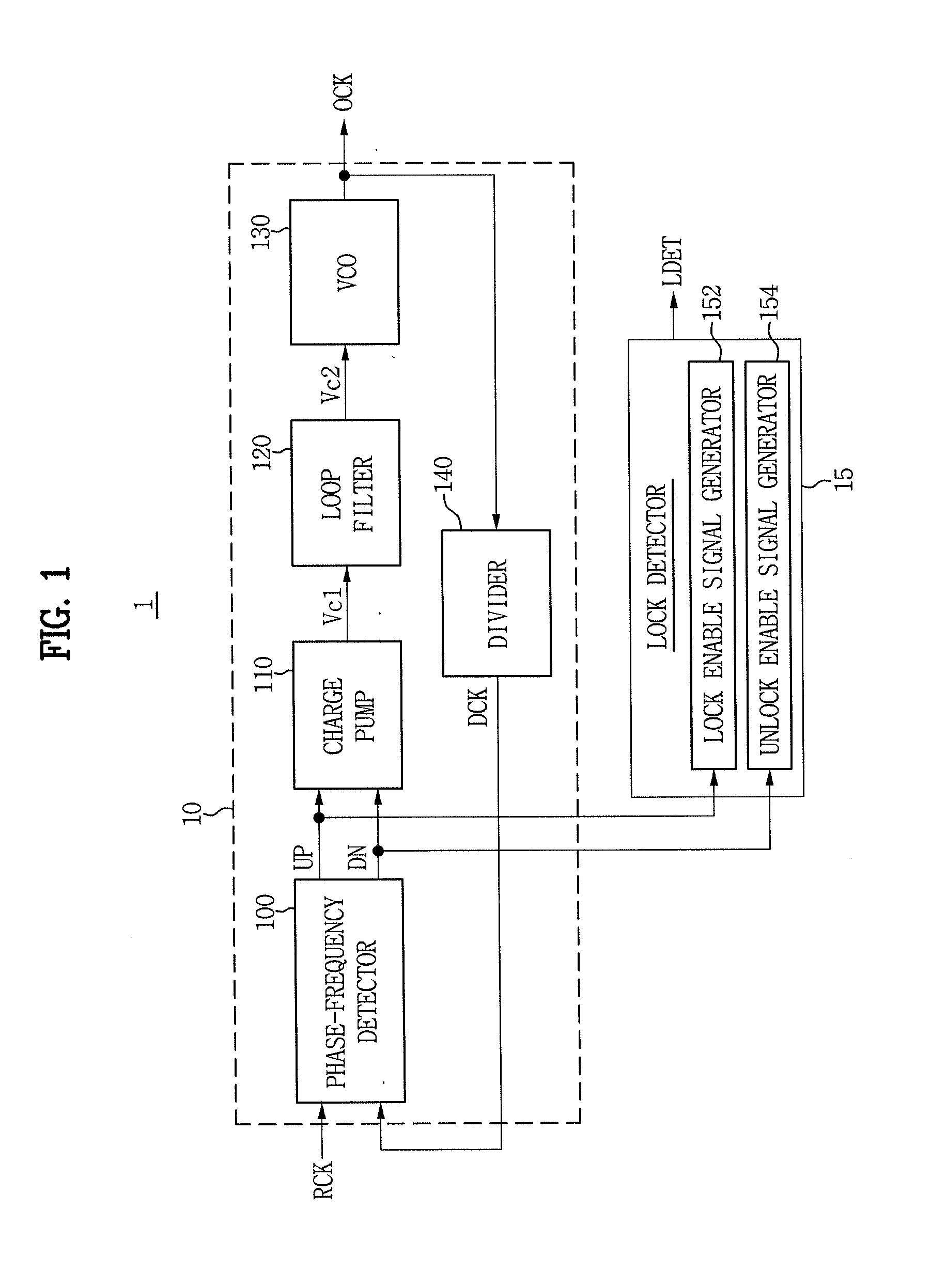
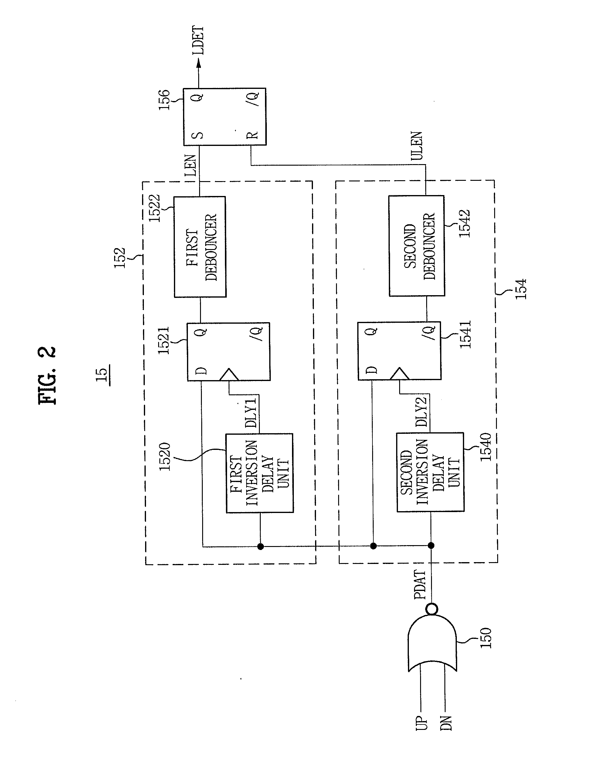
[0009]One or more embodiments may provide a lock detector configured to more stably determining a lock state or an unlock state of a PLL circuit in spite of noise, a PLL circuit including such a lock detector, and a method of detecting a lock, and a system including such a PLL circuit.

Problems solved by technology

For example, the reference value may become less than a value of jitter, which is an output noise typically caused by internal characteristics of the PLL circuit.
In this case, when the jitter occurs, the lock detection circuit may mistake the lock state for the unlock state and output a wrong output signal.
Conversely, when the reference value is increased due to external factors, the lock detection circuit may mistake the unlock state for the lock state and output a wrong output signal.
As described above, when the reference value per se is changed due to the external factors, a malfunction may become highly likely to occur in the PLL circuit, and a system may be unstable.

Method used


Image

  • Phase locked loop circuit, method of detecting lock, and system having the circuit
  • Phase locked loop circuit, method of detecting lock, and system having the circuit
  • Phase locked loop circuit, method of detecting lock, and system having the circuit

Examples


Embodiment Construction

[0028]Various embodiments will now be described more fully with reference to the accompanying drawings in which some embodiments are shown. These inventive concepts may, however, be embodied in different forms and should not be construed as limited to the embodiments set forth herein. Rather, these embodiments are provided so that this disclosure is thorough and complete and fully conveys the inventive concept to those skilled in the art. In the drawings, the sizes and relative sizes of layers and regions may be exaggerated for clarity. Like reference terms refer to like elements throughout the specification.

[0029]It will be understood that the term “and / or” includes any and all combinations of one or more of the associated listed items. It will be understood that, although the terms first, second, third, etc. may be used herein to describe various elements, these elements not be limited by these terms. These terms are only used to distinguish one element from another. Thus, a first...


PUM


Abstract

Provided are a phase locked loop (PLL) circuit, a lock detector employable with a PLL circuit, a system including such a PLL circuit and/or lock detector, and a method of detecting a lock/unlock state of a PLL circuit. The PLL circuit may include a clock generating circuit configured to generate an output clock signal having a predetermined frequency in synchronization with a reference clock signal. The lock detector may be configured to determine that the PLL circuit is in a lock state when a phase difference between the reference clock signal and the output clock signal is equal to or less than a first reference value, determine that the PLL circuit is in an unlock state when the phase difference between the reference clock signal and the output clock signal is greater than a second reference value, and generate a lock detection signal.

Description

CROSS-REFERENCE TO RELATED APPLICATION[0001]This application claims priority under 35 U.S.C. §119 to Korean Patent Application No. 10-2010-0024402 filed on MAR18, 2010, the disclosure of which is hereby incorporated by reference in its entirety.BACKGROUND[0002]1. Field[0003]Embodiments of the inventive concept relate to a lock detector, a phase locked loop (PLL) circuit including such a lock detector, a method of detecting a lock, and a system including such a lock detector and / or PLL circuit. More particularly, embodiments relate to a lock detector configured to be capable of stably determining a lock state and an unlock state of a PLL circuit, a method of detecting a lock, and a system including such a lock detector and / or PLL circuit.[0004]2. Description of the Related Art[0005]In general, a phase locked loop (PLL) circuit may be a basic circuit included in an electronic system, which may generate an output clock signal having a desired frequency and transmit the output clock sig...

Claims


Application Information

Patent Timeline
Patent Type & Authority Applications(United States)
IPC IPC(8): H03L7/08
CPCH03L7/095
Inventor JANG, TAE-KWANGPARK, JAE-JINKIM, JI-HYUN
Owner SAMSUNG ELECTRONICS CO LTD
Why Eureka
Try Eureka