
Pneumatic tire

a technology of pneumatic tires and tires, applied in the field of pneumatic tires, can solve problems such as wear resistance performance, achieve the effects of suppressing uneven wear of the block 331, improving the snow performance of the tire, and improving the wear resistance performance of the tir

Active Publication Date: 2020-03-31
THE YOKOHAMA RUBBER CO LTD
View PDF46 Cites 0 Cited by
  • Summary
  • Abstract
  • Description
  • Claims
  • Application Information

AI Technical Summary

Benefits of technology

This configuration enhances snow traction and wear durability by increasing edge components and ensuring uniform rigidity, resulting in improved snow performance and wear resistance.

Problems solved by technology

Configurations employing such a block pattern have the challenge of increasing wear resistance performance (wear durability performance and uneven wear resistance performance) of the blocks.

Method used


Image

  • Pneumatic tire
  • Pneumatic tire
  • Pneumatic tire

Examples


examples

[0120]FIG. 14 is a table showing results of performance testing of pneumatic tires according to embodiments of the present technology.

[0121]In the performance testing, a plurality of different test tires were evaluated for (1) snow performance and (2) wear resistance performance. The test tires with a tire size of 265 / 65R17 112H were mounted on a rim having a rim size of 17×8J, and an air pressure of 230 kPa and a maximum load as defined by JATMA were applied to the test tires. The test vehicle that the test tires were mounted on was a four wheel drive recreational vehicle (RV) with an engine displacement of 3500 cc.

[0122](1) Evaluation of snow performance: The test vehicle was driven on a snowy road surface of a snowy road test site, and the braking distance from a traveling speed of 40 km / h was measured. Then, the measurement results were expressed as index values with the result of the conventional example being defined as the reference (100). In this evaluation, larger values ar...


PUM


Abstract

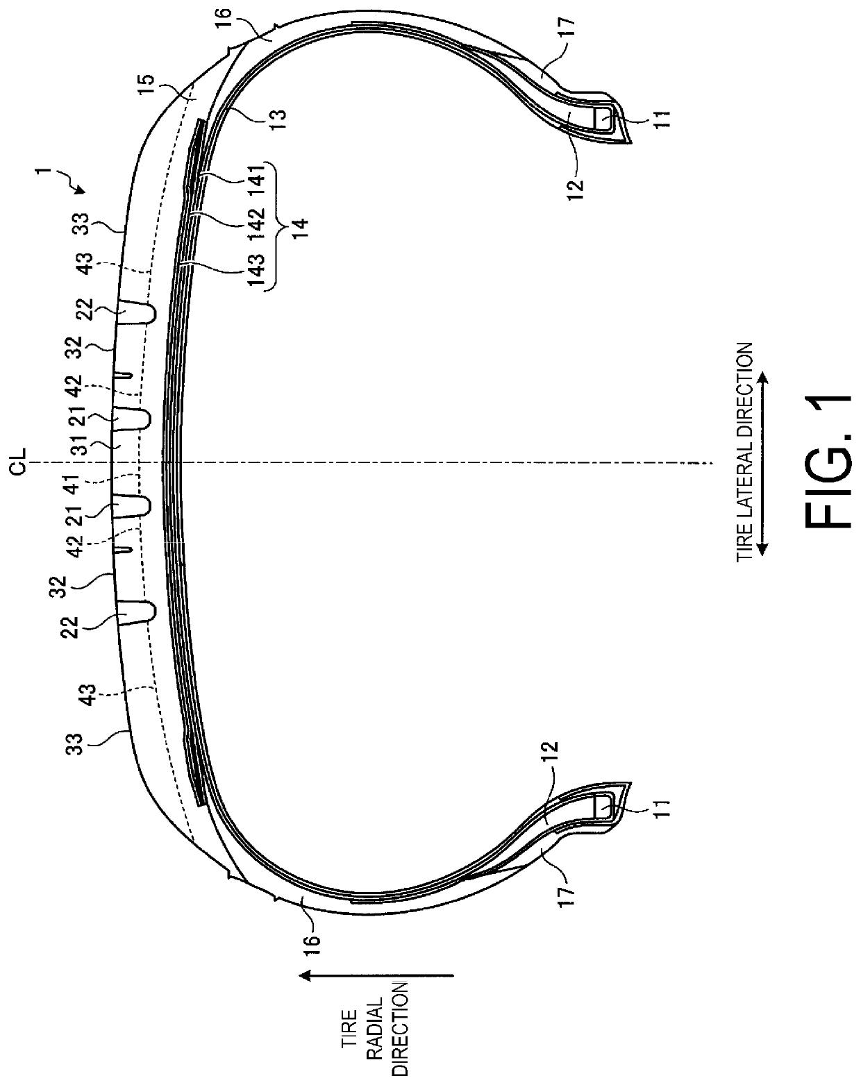
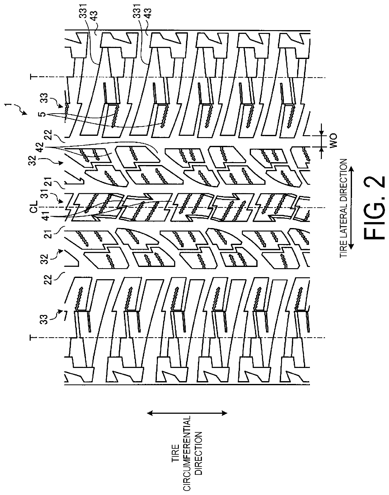
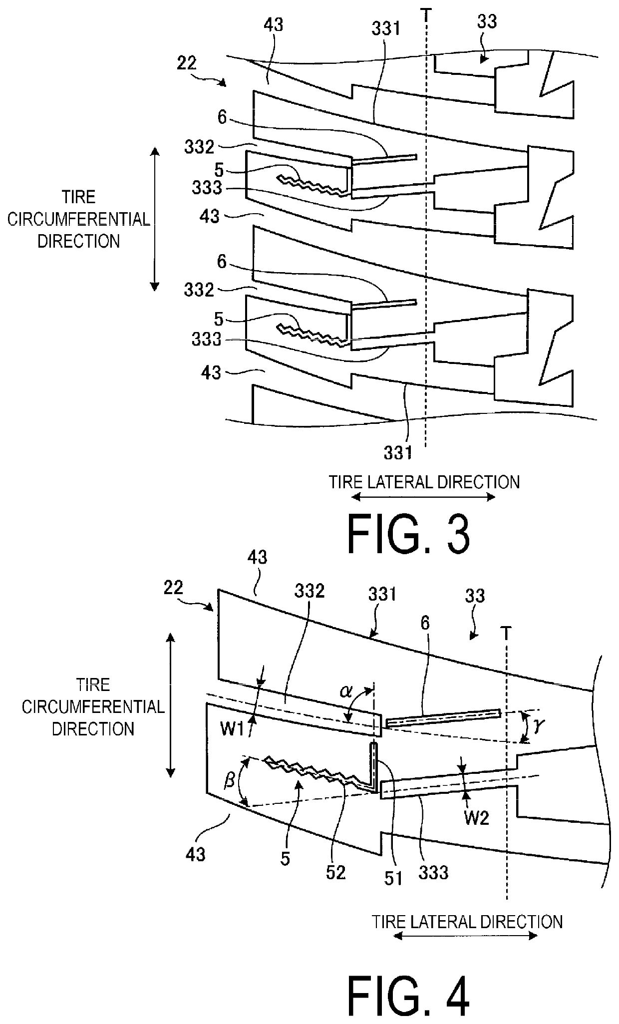
A pneumatic tire comprises a plurality of blocks arranged on a tire ground contact edge. The plurality of blocks each comprise at least one main sipe that comprises: a two-dimensional sipe portion extending in a tire circumferential direction, and a three-dimensional sipe portion extending in a tire lateral direction that connects to the two-dimensional sipe portion.

Description

TECHNICAL FIELD[0001]The present technology relates to a pneumatic tire and particularly relates to a pneumatic tire with improved snow performance and wear resistance performance.BACKGROUND ART[0002]To increase traction characteristics and improve snow performance, conventional pneumatic tires have typically employed a block pattern.[0003]The technology disclosed in Japanese Unexamined Patent Application Publication No. 2003-341306A is a known conventional pneumatic tire that is configured in this manner.[0004]Configurations employing such a block pattern have the challenge of increasing wear resistance performance (wear durability performance and uneven wear resistance performance) of the blocks.SUMMARY[0005]The present technology provides a pneumatic tire with improved snow performance and wear resistance performance.[0006]An embodiment of the present technology is a pneumatic tire comprising a plurality of blocks arranged on a tire ground contact edge; the plurality of blocks ea...

Claims


Application Information

Patent Timeline
Patent Type & Authority Patents(United States)
IPC IPC(8): B60C11/12B60C11/03B60C11/11
CPCB60C11/1236B60C11/1263B60C11/1218B60C11/0306B60C11/12B60C11/11B60C11/03B60C2011/1213B60C2011/1254B60C2011/1268
Inventor AKASHI, YASUTAKA
Owner THE YOKOHAMA RUBBER CO LTD
Learn More