
Surgical instrument with shiftable transmission

a technology of surgical instruments and transmission lines, applied in the field of surgical instruments with shiftable transmission lines, can solve the problems of insufficient motor output of existing telesurgical platforms, inconvenient development of a new telesurgical system for a particular surgical application,

Active Publication Date: 2020-04-07
INTUITIVE SURGICAL OPERATIONS INC
View PDF48 Cites 549 Cited by
  • Summary
  • Abstract
  • Description
  • Claims
  • Application Information

AI Technical Summary

Benefits of technology

The patent describes a surgical tool with a plurality of degrees of freedom (DOFs) that can be controlled by a surgeon using a remote arm. The tool has a distal end with a surgical end effector and a plurality of motor interfaces for driving the DOFs. The motor interfaces can be coupled to the effector components to shift the coupling between them. The tool can have a gripping device with a wrist that can roll, yaw, and pitch, and the DOFs can include a mechanism for actuating the surgical tool, a mechanism for actuating the gripping device with high force, a mechanism for causing the wrist to yaw, a mechanism for causing the wrist to pitch, and a mechanism for actuating the gripping device with low force. The camshaft can have multiple camshaft lobes to power and lock each DOF. The transmission can include a first gear train for driving the first DOF, a second gear train for driving the second DOF, and a third gear train for driving the third DOF.

Problems solved by technology

While many of the surgeries performed each year in the United States could potentially be performed in a minimally invasive manner, only a portion of the current surgeries use these advantageous techniques due to limitations in minimally invasive surgical instruments and the additional surgical training involved in mastering them.
Thus, the instrument is required to adapt to the telesurgical system, since development of a new telesurgical system for a particular surgical application is cost prohibitive.
However, issues arise when existing telesurgical platforms do not have the required amount of motor outputs for all of the mechanisms of a particular surgical instrument.

Method used


Image

  • Surgical instrument with shiftable transmission
  • Surgical instrument with shiftable transmission
  • Surgical instrument with shiftable transmission

Examples


Embodiment Construction

[0051]In the following description, various embodiments of the present invention will be described. For purposes of explanation, specific configurations and details are set forth in order to provide a thorough understanding of the embodiments. However, it will also be apparent to one skilled in the art that the present invention may be practiced without the specific details. Furthermore, well-known features may be omitted or simplified in order not to obscure the embodiment being described.

[0052]I. Minimally Invasive Teleassisted Surgery System

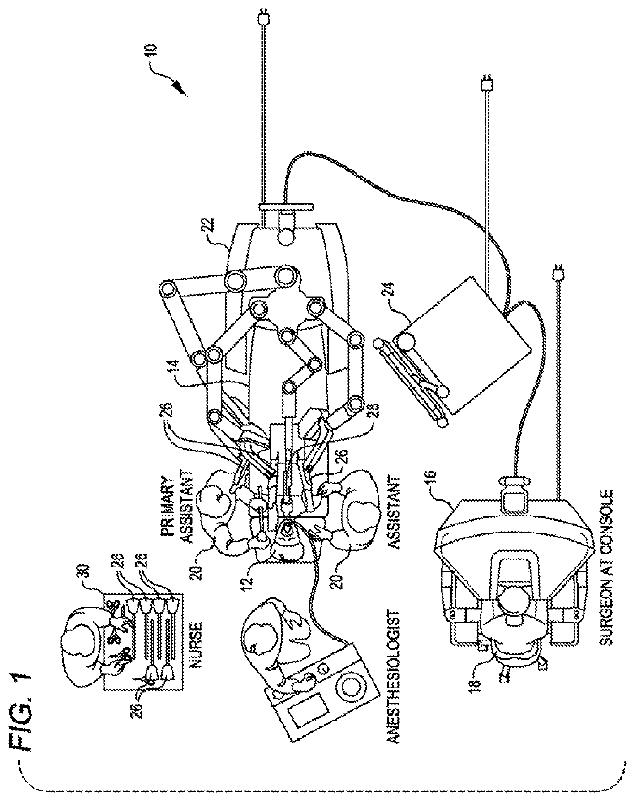
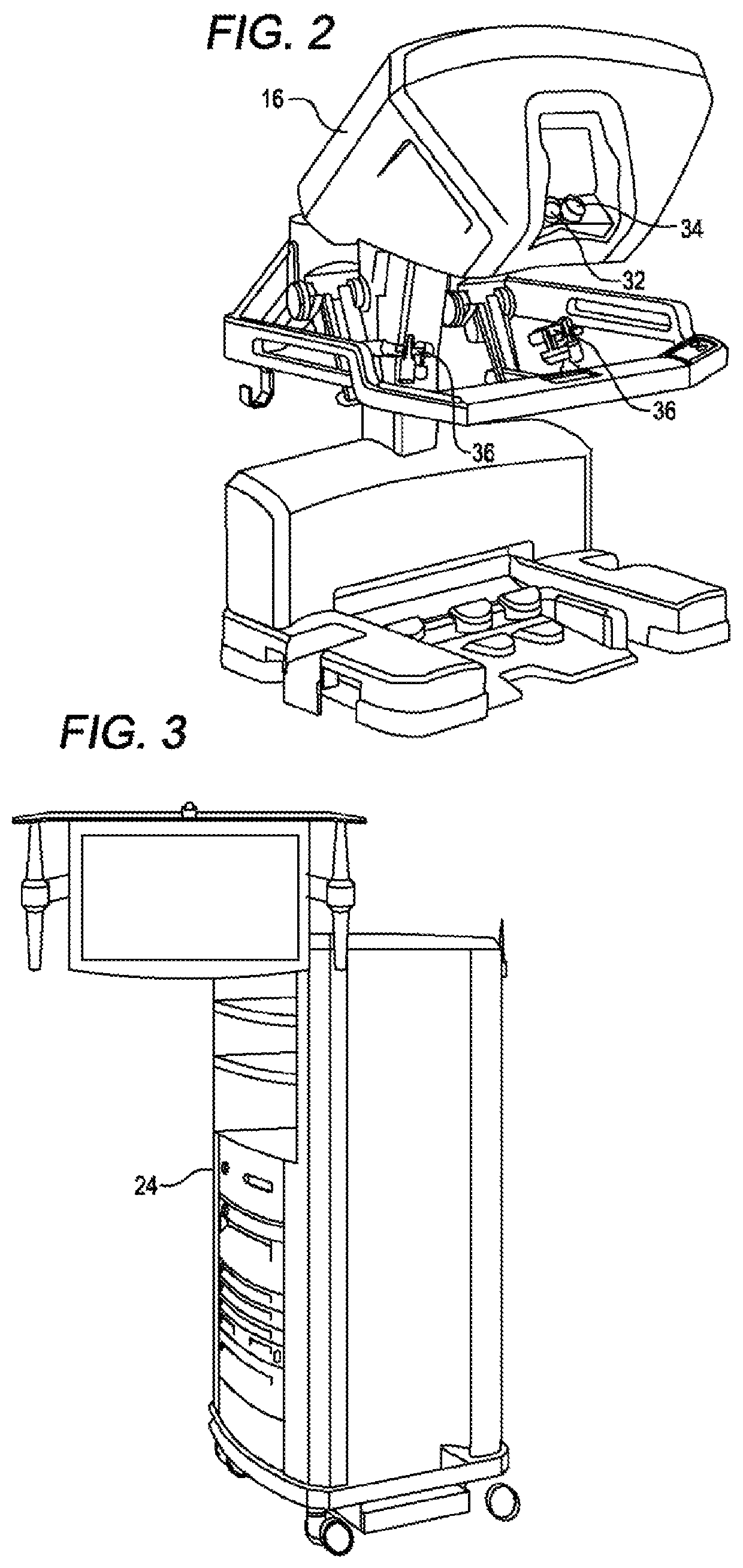
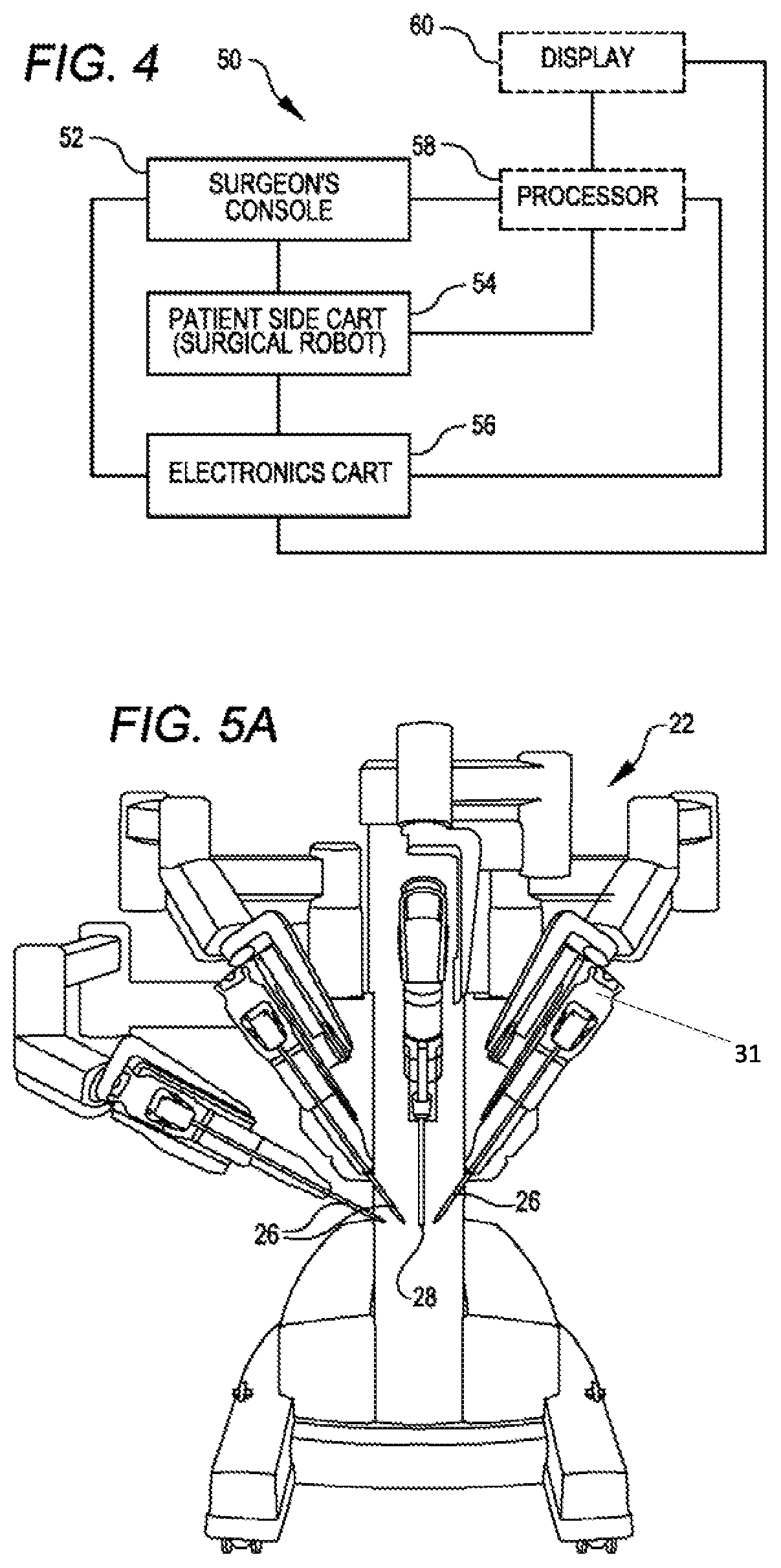
[0053]Referring now to the drawings, in which like reference numerals represent like parts throughout the several views, FIG. 1 is a plan view illustration of a Minimally Invasive Robotic Surgical (MIRS) system 10, typically used for performing a minimally invasive diagnostic or surgical procedure on a Patient 12 who is lying down on an Operating table 14. The system can include a Surgeon's Console 16 for use by a Surgeon 18 during the procedu...


PUM


Abstract

A surgical tool having an elongated shaft having a proximal end and distal end. A surgical end effector is located about the distal end. The surgical end effector has a plurality of effector mechanisms comprising a plurality of degree of freedoms. An effector body is located at the proximal end. The effector body includes a plurality of motor interfaces for driving the plurality of effector mechanisms. A transmission is coupled to the effector body.

Description

CROSS-REFERENCES TO RELATED APPLICATIONS[0001]This application is the U.S. national phase of International Application No. PCT / US15 / 23636, filed Mar. 31, 2015, which designated the U.S. and claims the benefit of U.S. Provisional Application No. 61 / 973,257, filed Mar. 31, 2014, all of which are incorporated by reference herein, in their entirety.BACKGROUND OF THE INVENTION[0002]Minimally invasive medical techniques are intended to reduce the amount of extraneous tissue that is damaged during diagnostic or surgical procedures, thereby reducing patient recovery time, discomfort, and deleterious side effects. One effect of minimally invasive surgery, for example, is reduced post-operative hospital recovery times. Because the average hospital stay for a standard surgery is typically significantly longer than the average stay for an analogous minimally invasive surgery, increased use of minimally invasive techniques could save millions of dollars in hospital costs each year. While many of...

Claims


Application Information

Patent Timeline
Patent Type & Authority Patents(United States)
IPC IPC(8): A61B34/30A61B34/00B25J9/16A61B17/29A61B34/37A61B17/00
CPCA61B34/37A61B34/30A61B34/70B25J9/1669A61B17/29A61B2017/00477A61B2034/305
Inventor BAILEY, DAVID W.ROGERS, THEODORE W.DEYANOV, RUMENLATHROP, RAYBRISSON, GABRIEL
Owner INTUITIVE SURGICAL OPERATIONS INC
Learn More