Cover for bracket of orthodontic appliance

a technology for orthodontic appliances and brackets, applied in dental tools, dental surgery, medical science, etc., can solve the problems of orthodontic patients, brackets on the exposed face of teeth to be unappealing, general unattractive, etc., and achieve the effect of enhancing the appearance of dental appliances, easy removal, and easy removal

Active Publication Date: 2020-04-21
DARLING STEVEN +1
View PDF28 Cites 5 Cited by
  • Summary
  • Abstract
  • Description
  • Claims
  • Application Information

AI Technical Summary

Problems solved by technology

While dental braces are highly effective and still one of the most commonly used orthodontic appliance for straightening and aligning teeth, they are generally unattractive.
In particular, many orthodontic patients find the brackets on the exposed face of the teeth to be unappealing and they may even feel embarrassed and reluctant to smile.
Accordingly, while the various elastomeric ligation devices proposed in the past have been effective to conceal the generally unsightly bracket of orthodontic appliances, they are not suited to be attached or removed by the patient.
Thus, the patient is not able to remove these elastomeric ligation devices each night or when desired, such as when brushing the teeth or simply to remove or interchange different cover devices over the brackets.

Method used


Image

  • Cover for bracket of orthodontic appliance
  • Cover for bracket of orthodontic appliance
  • Cover for bracket of orthodontic appliance

Examples


first embodiment

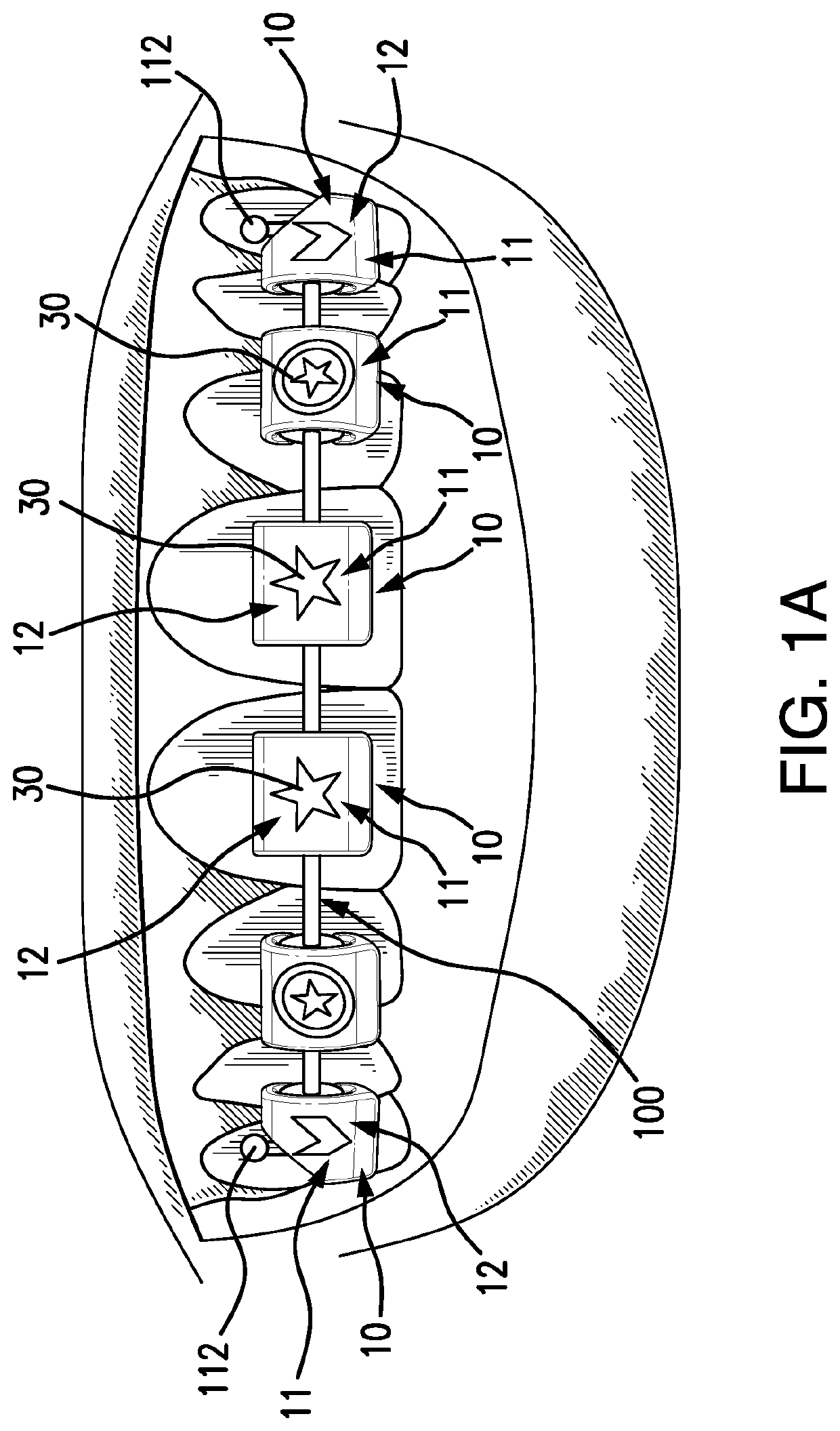
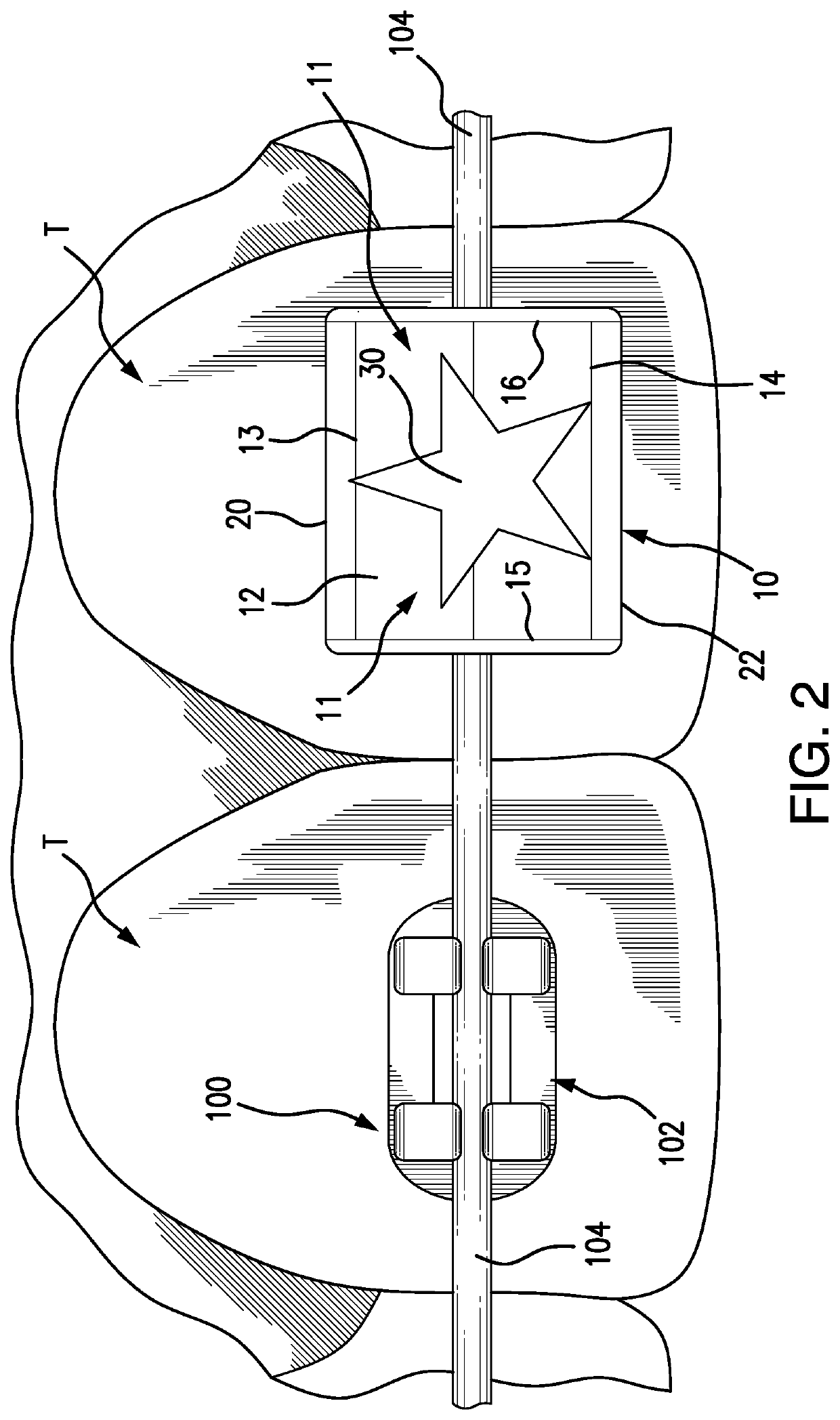
[0044]Referring to FIGS. 2-8, the cover device 10 of the present invention is shown and includes a main plate 11 having an outer front face 12, a top end 13, a bottom end 14, opposite side edges 15, 16 and a rear side 18. A top claw 20 is integrally formed with the main plate 11 and extends from the top end 13 of the main plate and curls back and downwardly behind the main plate, terminating at a distal end 24, as best seen in FIGS. 3A-3B and FIG. 8. A bottom claw 22 is integrally formed with the main plate 11 and extends from the bottom end 14 of the main plate 11 and curls back and upwardly behind the main plate 11, terminating at a distal end 26, so that the distal ends 24, 26 of the upper and lower claws are spaced in opposing relation to one another and spaced from the rear side 18 of the main plate 11, as seen in FIGS. 3A-3B and FIG. 8.

[0045]In a preferred embodiment, the cover device 10 is formed of a plastic composition or other similar composition that is generally rigid, b...

second embodiment

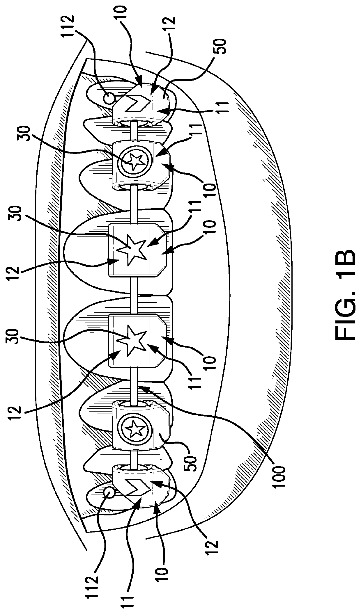
[0051]Referring to FIGS. 14 and 17, the cover device 10 includes at least one stop member centrally positioned on the rear side for discouraging lateral movement of the cover device 10 relative to the bracket 102. As seen in FIG. 17, a centrally positioned rib 54 extends from the rear side 18 of the main plate 12 to an inner side of both the top claw 20 and the bottom claw 22 to provide stop members 54. These two centrally positioned stop members 54 (i.e., upper and lower) are positioned between left and right prong sets of the bracket 102 (see FIG. 2) so that lateral movement of the cover device 10 relative to the bracket 102 will cause the stop members 54 to engage the prong sets of the bracket 102. This helps to prevent unwanted lateral movement and possible separation of the cover device 10 from the bracket 102. It should be noted, however, that with sufficient lateral force, the stop members 54 may ride over the prong sets of the bracket 102 and thereby allow for separation and...


PUM


Abstract

A cover device formed of a plastic or similar composition is structured for removable attachment over a bracket of an orthodontic appliance and includes a main plate with an outer front face, and top and bottom claws integrally formed with the main plate, curling behind the main plate, and each terminating at distal ends in spaced, opposing relation to each other behind the main plate. The main plate is bowed outwardly from top to bottom to allow the claws to flex away from each other and snap over the bracket upon application of inward pressure on the front face while the claws are pressed against the bracket, to thereby attach the cover to the bracket, with the bracket concealed from view behind the cover device. The front face may include an ornamental design. In another embodiment, the cover device includes a bottom tab for cooperating engagement with a removal tool.

Description

[0001]This non-provisional patent application is based on provisional patent application Ser. No. 62 / 512,922 filed May 31, 2017.BACKGROUND OF THE INVENTIONField of the Invention[0002]This invention relates to accessory devices for orthodontic appliances and, more particularly, to a cover device for attachment to individual brackets on a patients teeth to provide an enhanced appearance of the orthodontic appliance without producing any tractive force on the arch wire. The invention may further include a tool that can be used by the patient to easily remove the cover device from the bracket.Discussion of the Related Art[0003]Orthodontic appliances commonly referred to as “dental braces” typically include brackets that are cemented to the outer facing surface of the patient's teeth and an arch wire that is held by the brackets and tightened to provide desired forces for aligning and straightening the patient's teeth. Traditional dental braces use elastic ties (o-ring ligators) that are...

Claims


Application Information

Patent Timeline
Patent Type & Authority Patents(United States)
IPC IPC(8): A61C3/00A61C7/28A61C7/12A61C19/10
CPCA61C7/28A61C7/125A61C19/10A61C2201/002A61C2203/00
Inventor DARLING, STEVENDARLING, JANIS
Owner DARLING STEVEN
Why Eureka
Try Eureka