Wireless Head Mounted Display with Differential Rendering and Sound Localization

a head mounted display and differential rendering technology, applied in the field of prediction rf beamforming for transmission, can solve the problems of user inconvenience, high bandwidth and stable connection, and the processing resources required to generate the video for rendering on the hmd, so as to reduce the size of image data, and improve the image quality.

Active Publication Date: 2017-02-16
SONY COMPUTER ENTERTAINMENT INC
View PDF7 Cites 209 Cited by
  • Summary
  • Abstract
  • Description
  • Claims
  • Application Information

AI Technical Summary

Benefits of technology

[0017]In some implementations, a region of the view towards which the gaze of the user is directed is rendered at a higher image quality setting than other regions of the view, the other regions of the view being rendered at a lower image quality setting to reduce a size of the image data.

Problems solved by technology

However, the processing resources required to generate the video for rendering on the HMD are considerable and therefore handled by a separate computing device, such as a personal computer or a game console.
However, such video entails transmission of large amounts of data, requiring high bandwidth and a stable connection.
However, the presence of a wire that connects to the HMD can be bothersome to the user, as it may contact the user and detract from the immersive experience of using the HMD.
Furthermore, the wired connection may inhibit the user's freedom of movement, as the user must be mindful of not over-extending the wire, and must avoid any movement which might cause disconnection or damage the wire.
Furthermore, the presence of the wire presents a tripping hazard, which is amplified by the fact that the user cannot see the real environment while using the HMD.

Method used


Image

  • Wireless Head Mounted Display with Differential Rendering and Sound Localization
  • Wireless Head Mounted Display with Differential Rendering and Sound Localization
  • Wireless Head Mounted Display with Differential Rendering and Sound Localization

Examples


Embodiment Construction

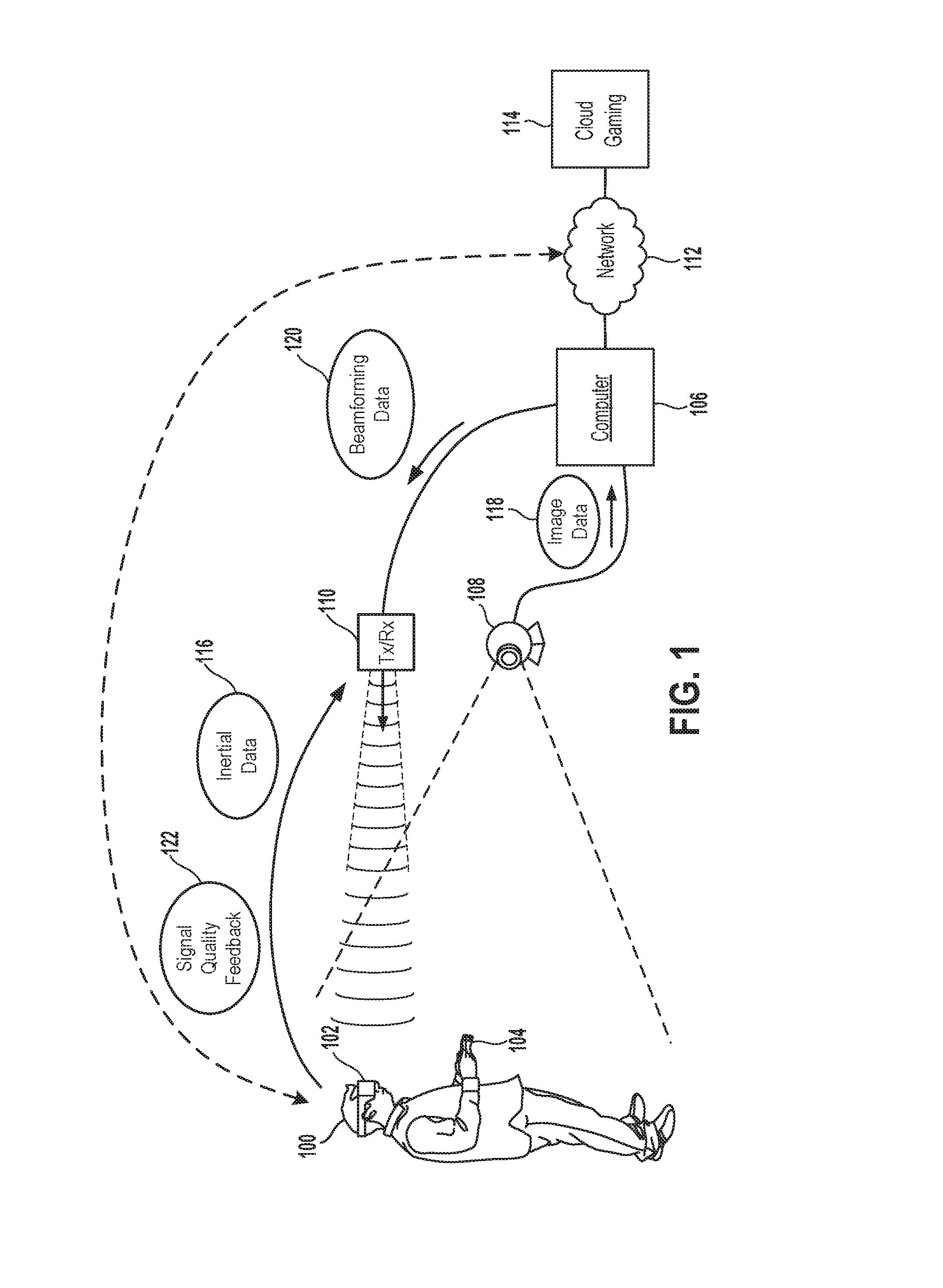
[0057]The following implementations of the present disclosure provide devices, methods, and systems relating to predictive RF beamforming for a head mounted display (HMD).

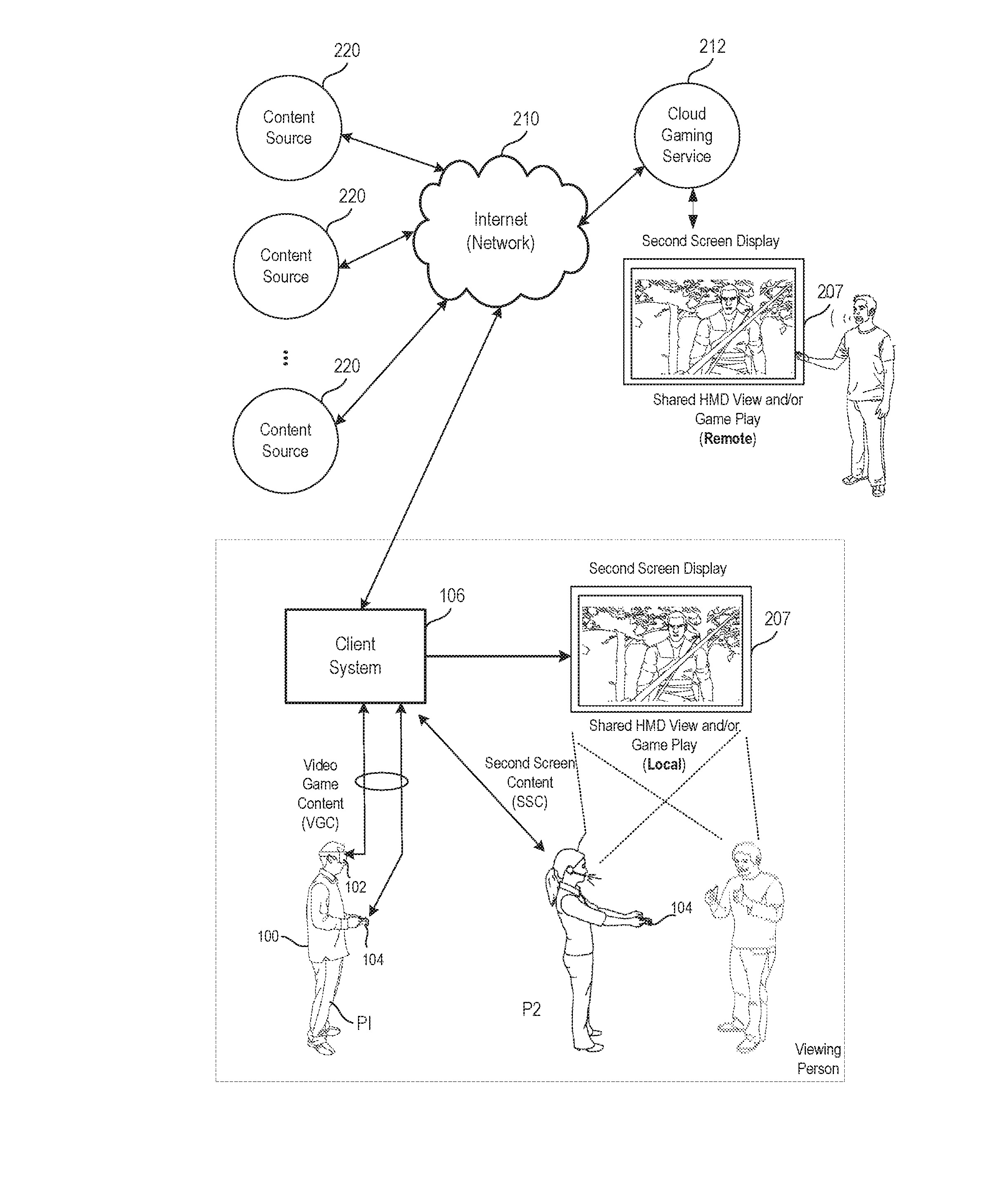
[0058]In various implementations, the methods, systems, image capture objects, sensors and associated interface objects (e.g., gloves, controllers, peripheral devices, etc.) are configured to process data that is configured to be rendered in substantial real time on a display screen. The display may be the display of a head mounted display (HMD), a display of a second screen, a display of a portable device, a computer display, a display panel, a display of one or more remotely connected users (e.g., whom may be viewing content or sharing in an interactive experience), or the like.

[0059]It will be obvious, however, to one skilled in the art, that the present disclosure may be practiced without some or all of these specific details. In other instances, well known process operations have not been described in detail i...


PUM


Abstract

A method is provided, including the following method operations: receiving captured images of an interactive environment in which a head-mounted display (HMD) is disposed; receiving inertial data processed from at least one inertial sensor of the HMD; analyzing the captured images and the inertial data to determine a current and predicted future location of the HMD; using the predicted future location of the HMD to adjust a beamforming direction of an RF transceiver towards the predicted future location of the HMD; tracking a gaze of a user of the HMD; generating image data depicting a view of a virtual environment for the HMD, wherein regions of the view are differentially rendered; generating audio data depicting sounds from the virtual environment, the audio data being configured to enable localization of the sounds by the user; transmitting the image data and the audio data via the RF transceiver to the HMD.

Description

CLAIM OF PRIORITY[0001]This application claims priority as a continuation-in-part of U.S. application Ser. No. 15 / 283,138, filed Sep. 30, 2016, entitled “Predictive RF Beamforming for Head Mounted Display.”[0002]This application also claims priority as a continuation-in-part of U.S. application Ser. No. 14 / 206,849, filed Mar. 12, 2014, entitled Image Rendering Responsive to User Actions in Head Mounted Display,” which claims priority to U.S. Provisional Application No. 61 / 832,755, filed Jun. 7, 2013.[0003]This application also claims priority as a continuation-in-part of U.S. application Ser. No. 14 / 706,575, filed May 7, 2015, entitled “Sound Localization for User In Motion,” which is a continuation of U.S. application Ser. No. 13 / 478,582 filed May 23, 2012, (now U.S. Pat. No. 9,037,468 issued May 19, 2015), which claims priority to U.S. Provisional Application No. 61 / 523,100, filed Aug. 12, 2011, and 61 / 539,676, filed Sep. 27, 2011.[0004]The disclosures of these applications are in...

Claims


Application Information

Patent Timeline
Patent Type & Authority Applications(United States)
IPC IPC(8): G06F3/01G06F3/16G06T3/40G09G5/14A63F13/211A63F13/53A63F13/30A63F13/213A63F13/25G06T7/00H04S7/00
CPCG06F3/013H04S2420/01G06F3/16G06T3/40G09G5/14H04S7/304A63F13/53A63F13/30A63F13/213A63F13/25A63F13/211G09G2340/0407G09G2354/00H04S2400/11G06T7/0042G06F3/147G09G3/003G09G2370/16G06F3/167H04S7/303A63F2300/6081A63F2300/6615A63F13/54A63F13/32
Inventor TOKUBO, TODDOSMAN, STEVENSTAFFORD, JEFFREY ROGERMAO, XIADONGBLACK, GLENN
Owner SONY COMPUTER ENTERTAINMENT INC
Why Eureka
Try Eureka