System-level approach to goal-driven design

a system-level approach and design technology, applied in the field of computer-aided design, can solve the problems of inability to account for cad tools, inability to design individual parts,

Active Publication Date: 2020-04-21
AUTODESK INC
View PDF11 Cites 6 Cited by
  • Summary
  • Abstract
  • Description
  • Claims
  • Application Information

AI Technical Summary

Benefits of technology

[0013]At least one advantage of the techniques described herein is that each system component can be optimized independently or in relation to other components in the system. Accordingly, the entire system can be optimized relative to system-level design objectives.

Problems solved by technology

First, conventional CAD tools usually can only be used to design individual parts. However, the design criteria associated with each part are usually constrained by other parts in the overall system. In the bicycle example, the particular length of each gear tooth in the chain ring would be constrained by the anticipated amount of torque needed to be transferred to the chain, which, in turn, would be driven by the crankshaft length. Conventional CAD tools generally do not account for the system-level context within which each individual part resides.
Second, conventional CAD tools usually require the engineer to design each individual component of a system and then assemble those components together, even when the ultimate assembly falls within a well-known class of structures. In the bicycle example, the engineer would be required to design the chain ring, the crankshafts, the pedals, and the chain and then physically organize those components into the desired system-level configuration. However, bicycle chain assemblies are well known bicycle systems. Consequently, the conventional design approach requires needless repetition of known tasks.
Finally, despite the fact that centuries of engineering knowledge exists, conventional CAD tools have no way to draw from this knowledge base for the benefit of the current designer or engineer.
Having to re-design well understood elements can lead to extended design times and increased frustration on the part of designers and engineers.
In sum, conventional CAD tools (i) are only applicable to individual parts, (ii) cannot configure assemblies of parts in meaningful ways, and (iii) cannot benefit from available engineering knowledge.

Method used


Image

  • System-level approach to goal-driven design
  • System-level approach to goal-driven design
  • System-level approach to goal-driven design

Examples


Embodiment Construction

[0033]In the following description, numerous specific details are set forth to provide a more thorough understanding of the present invention. However, it will be apparent to one of skill in the art that the present invention may be practiced without one or more of these specific details.

System Overview

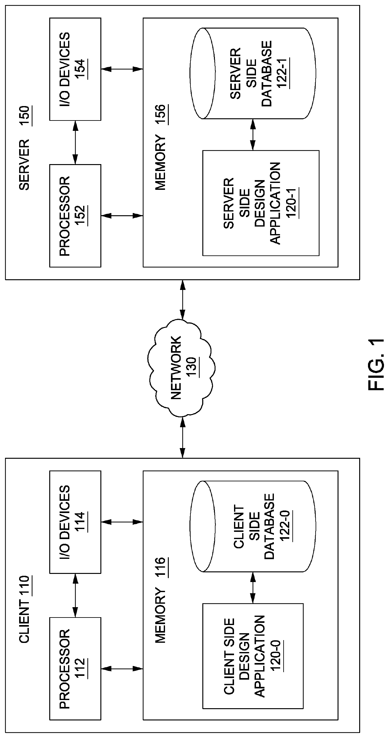
[0034]FIG. 1 illustrates a system 100 configured to implement one or more aspects of the present invention. As shown, system 100 includes, without limitation, a client 110 coupled via a network 130 to a server 150. Client 110 may be any technically feasible variety of client computing device, including a desktop computer, laptop computer, mobile device, and so forth. Network 150 may be any technically feasible set of interconnected communication links, including a local area network (LAN), wide area network (WAN), the World Wide Web, or the Internet, among others. Server 150 may be any technically feasible type of server computing device, including a remote virtualized instance of a c...


PUM


Abstract

A design application is configured to perform a system-level optimization of a collection of system components. The design application iteratively executes a multi-objective solver to optimize structural and functional relationships between the system components in order to meet global design criteria and generate a system design. The design application initializes the design process by extracting from a knowledge base system templates having taxonomic, structural, or functional attributes relevant to the system design. The design application generates the knowledge base by mining taxonomic, structural, and functional relationships from a corpus of engineering texts.

Description

CROSS-REFERENCE TO RELATED APPLICATIONS[0001]This application claims the benefit of U.S. provisional patent application titled “Dreamcatcher: System-Level Approach to Goal-Driven Design,” filed on Jul. 23, 2015 and having Ser. No. 62 / 196,264. The subject matter of this related application is hereby incorporated herein by reference.BACKGROUND OF THE INVENTION[0002]Field of the Invention[0003]Embodiments of the present invention relate generally to computer-aided design and, more specifically, to a system-level approach to goal-driven design.[0004]Description of the Related Art[0005]Engineers often use computer-aided design (CAD) tools to design individual parts of larger systems. For example, an engineer may use a conventional CAD tool to design the chain ring of a bicycle to meet certain design criteria. During the design process, engineers typically employ a workflow that involves formulating the problem to be solved, conceptualizing a potential design, using a CAD tool to generate...

Claims


Application Information

Patent Timeline
Patent Type & Authority Patents(United States)
IPC IPC(8): G06F16/2458G06N5/02
CPCG06F30/17G06F30/00G06F16/2477G06N5/022G06F30/15G06F2111/02
Inventor CHEONG, HYUNMINLI, WEIIORIO, FRANCESCO
Owner AUTODESK INC
Why Eureka
Try Eureka