Sprayer fluid operation system

a fluid operation system and fluid filling technology, applied in the field of fluid filling operation systems, can solve the problems of heavy, complicated, heavy, and expensive, and achieve the effects of reducing the number of fluid filling pumps, pressurizing, and reducing the number of spraying

Active Publication Date: 2020-04-28
JOHN DEERE FAB HORST +1
View PDF4 Cites 11 Cited by
  • Summary
  • Abstract
  • Description
  • Claims
  • Application Information

AI Technical Summary

Problems solved by technology

Due to the large amounts of fluid and different fluid solutions involved, the control pumps for fluid filling, cleansing, mixing, agitating, spraying and pressurizing are very complicated, bulky, heavy and expensive.

Method used


Image

  • Sprayer fluid operation system
  • Sprayer fluid operation system
  • Sprayer fluid operation system

Examples


Embodiment Construction

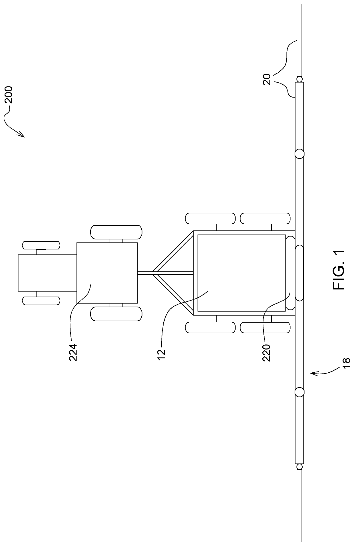
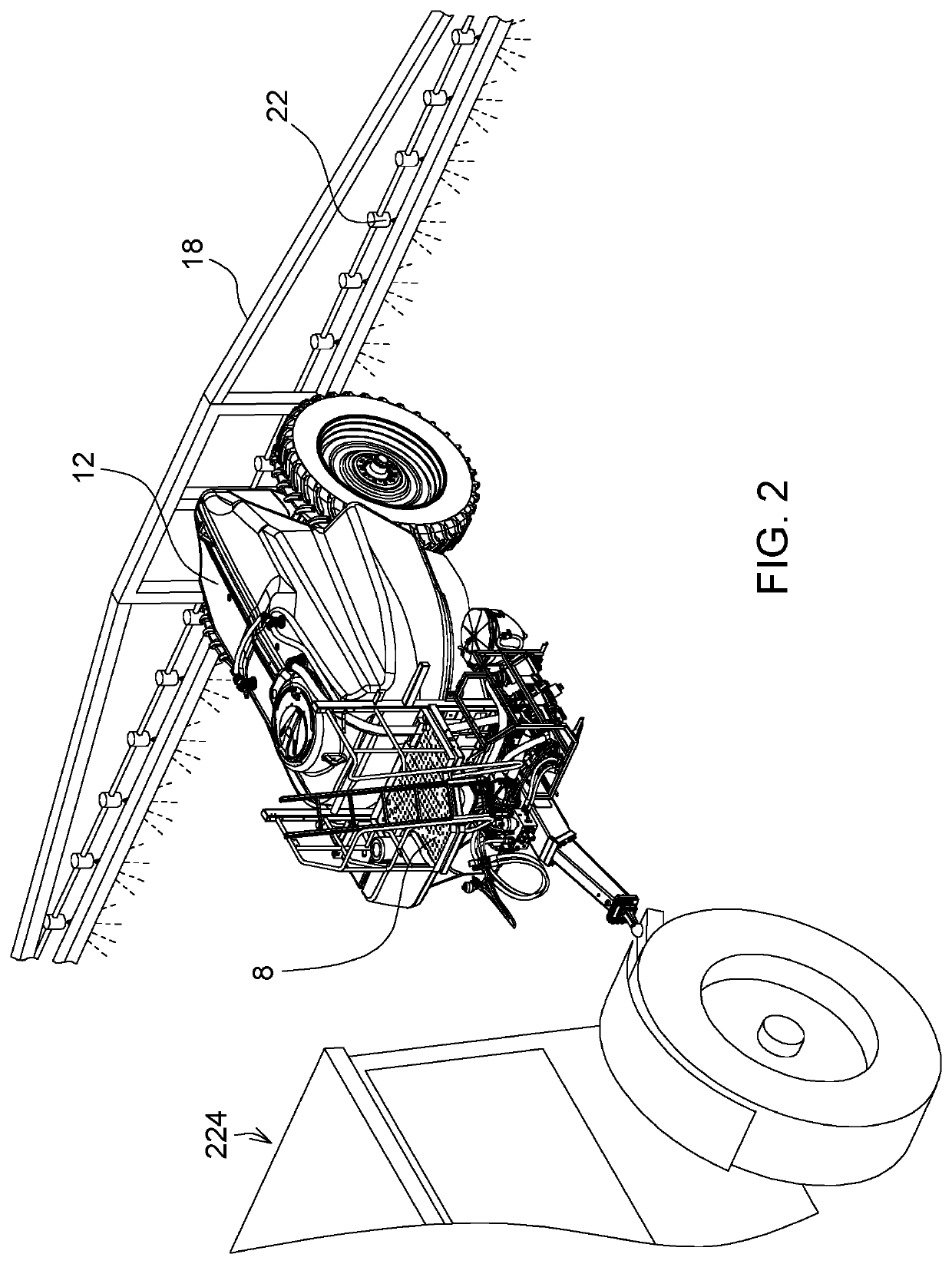
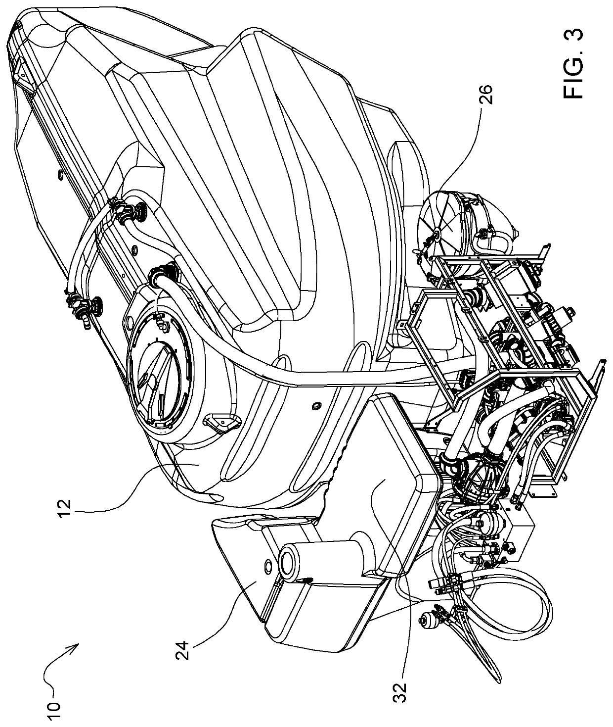
[0013]This disclosure provides example embodiments of trailed sprayers having an integrated fluid operation system that provides two strategically located together, integrated pumps (e.g. centrifugal impeller pumps) that can perform fast, or even simultaneous fluid operations such as tank filling along with rinsing, spraying, diluting, or agitating. Each of the pumps is capable of performing more than one function so that both pumps either perform the same or different functions simultaneously. For example, the filling speed can be increased when both pumps perform simultaneous filling of a single solution tank. In some embodiments, instead of two separate pumps each with its own hydraulic or electronic regulators, there is a shared mechanism. Alternatively, when each pump simultaneously performs a different function such as filling and rinsing, one pump is directly connected to the solution tank, while the other pump is directly connected to the rinse tank. By enabling the capabili...


PUM


Abstract

Embodiments of a spray fluid operation system include a fluid flow circuit that provides several sprayer features while using a minimum number of fluid pumps. In an agricultural setting, a first pump (one function of which is filling) is integrated with a second pump (one function of which is spraying) and both located compactly underneath the solution tank. In some embodiments that include only two pumps, they are centrifugal impeller pumps. Each of the two pumps is capable of performing more than one function. Together, they provide self-primed filling, auto dilution, eductor rinsing, and so on, in a fluid-isolated manner to avoid fluid contamination.

Description

RELATED APPLICATIONS[0001]This disclosure relates generally to fluid operation systems such as used in agricultural sprayers. This patent application also claims priority to U.S. Provisional Patent Application Ser. No. 62 / 189,017, filed Jul. 6, 2015, and entitled, SPRAYER FLUID OPERATION SYSTEM, the contents of which are incorporated herein by reference.FIELD[0002]This disclosure relates generally to fluid operation systems such as used in agricultural sprayers.BACKGROUND[0003]Large system sprayers apply nutrients, herbicides, paints, chemicals and other liquids such as those used on agricultural crops or industrial surfaces. Due to the large amounts of fluid and different fluid solutions involved, the control pumps for fluid filling, cleansing, mixing, agitating, spraying and pressurizing are very complicated, bulky, heavy and expensive. Further, different countries may have different regulations as to the type of fluids and concentration levels.SUMMARY OF THE DISCLOSURE[0004]Vario...

Claims


Application Information

Patent Timeline
Patent Type & Authority Patents(United States)
IPC IPC(8): A01M7/00B05B9/04
CPCA01M7/0082A01M7/0089A01M7/0053A01M7/0042B05B9/0423B05B9/0406
Inventor ENGELBRECHT, JOSHUA J.VAN GILS, MARTIJN
Owner JOHN DEERE FAB HORST
Why Eureka
Try Eureka