
Braking device for dual-bearing reel

a braking device and reel technology, applied in the direction of reels, applications, fishing, etc., can solve the problem of resonance and the risk that the braking force with respect to the spool will change significantly from a set value, and achieve the effect of stably applying the braking force to the spool

Active Publication Date: 2020-05-05
SHIMANO INC
View PDF11 Cites 0 Cited by
  • Summary
  • Abstract
  • Description
  • Claims
  • Application Information

AI Technical Summary

Benefits of technology

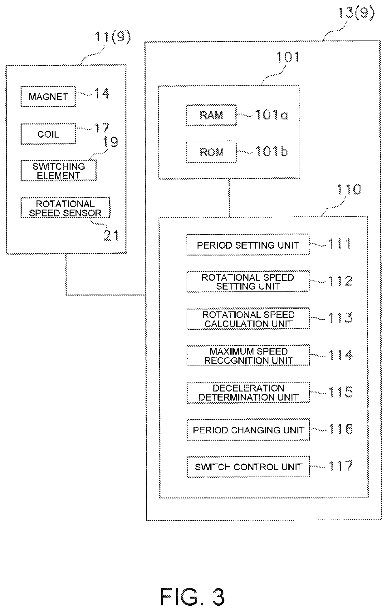
[0008]In the present braking device for a dual-bearing reel, since the spool control unit has a period changing unit, it is possible to change the prescribed period for braking the spool in accordance with the period of the current that flows through the coil due to the rotation of the spool. As a result, the problem described above can be solved, and it is possible to stably apply a braking force to the spool.
[0010]Here, by changing the prescribed period for braking the spool in accordance with the rotational speed of the spool, it is possible to stably apply the braking force to the spool.
[0012]Here, by changing the prescribed period for braking the spool based on the rotational speed for changing the period, it is possible to stably apply the braking force to the spool.
[0020]Here, by changing the prescribed period for braking the spool after the rotational speed of the spool reaches the maximum rotational speed, it is possible to stably apply the braking force to the spool.
[0021]In the present invention, it is possible to stably apply the braking force to the spool in the braking device for a dual-bearing reel.

Problems solved by technology

In this case, when the switching period is a prescribed ratio, a non-negative integer multiple, for example, of the period through which current flows through the coil due to the rotation of the spool, there is the risk that the braking force with respect to the spool will change significantly from a set value due to resonance.

Method used


Image

  • Braking device for dual-bearing reel
  • Braking device for dual-bearing reel
  • Braking device for dual-bearing reel

Examples


Embodiment Construction

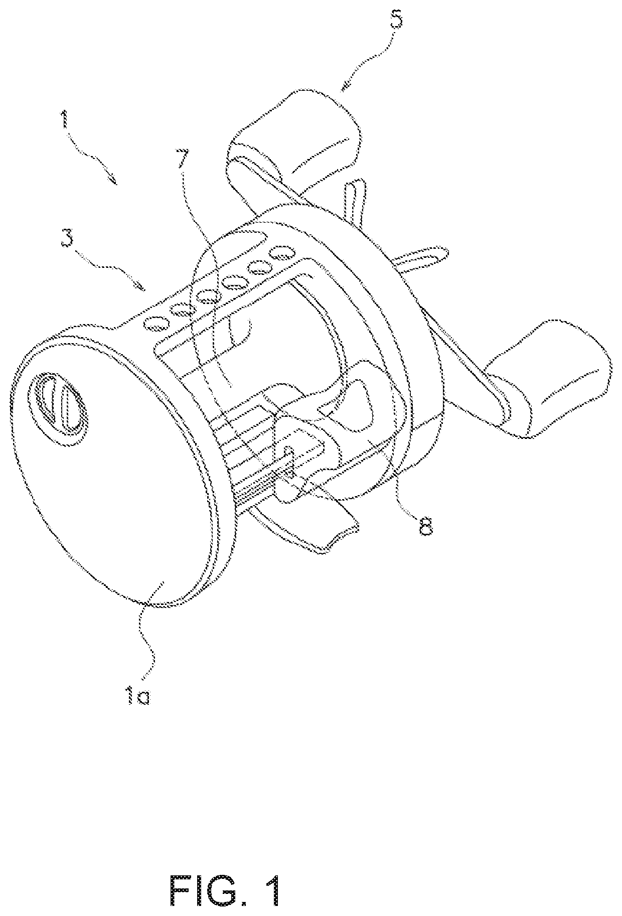
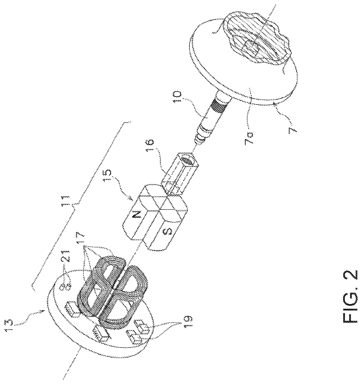
[0026]As shown in FIG. 1, a dual-bearing reel 1, applied to a first embodiment of the present invention, comprises a reel body 3, a handle 5, a spool 7, and a spool braking device (spool brake) 9 (refer to FIG. 2: one example of a braking device (brake) for a dual-bearing reel).

[0027]The handle 5 is disposed on the reel body 3 so as to be rotatable. Fishing line is wound around the spool 7. The spool 7 is mounted on the reel body 3 so as to be rotatable. When clutch 8 is in the ON-state, for example, the spool 7 rotates relative to the reel body 3 in conjunction with the rotation of the handle 5. On the other hand, when the clutch 8 is in the OFF-state, the spool 7 rotates freely with respect to the reel body 3.

[0028]The spool braking device 9 is a device for braking the spool 7 that is rotatably mounted on the reel body 3. The spool braking device 9 is disposed inside the reel body 3. As shown in FIG. 2, the spool braking device 9 comprises a spool braking unit (spool brake) 11 (on...


PUM


Abstract

A braking device for a dual-bearing reel for braking a spool rotatably mounted on a reel body, includes a spool brake and a spool controller. The spool brake is configured to brake the spool by electromagnetic induction during casting of a fishing line. The spool controller is configured to control a braking force of the spool brake by controlling an ON / OF-state of current that is generated due to the electromagnetic induction at a prescribed period. The spool controller has a period changer configured to change the prescribed period for braking the spool.

Description

CROSS-REFERENCE TO RELATED APPLICATIONS[0001]This application claims priority to Japanese Patent Application No. 2018-088625, filed on May 2, 2018. The entire disclosure of Japanese Patent Application No. 2018-088625 is hereby incorporated herein by reference.BACKGROUNDField of the Invention[0002]The present invention relates to a spool braking device for a dual-bearing reel, in particular, to a spool braking device for a dual-bearing reel that brakes a spool rotatably mounted on a reel body.Background Art[0003]A conventional dual-bearing reel includes a spool braking device that brakes a spool in order to prevent backlash at the time of casting (refer to Japanese Published Unexamined Application No. 2004-208631). In this spool braking device, when the spool rotates, a magnet that rotates integrally with the spool and a coil disposed on a reel body rotate relative to each other. In this state, using ON / OFF-control of the switch at a set period, current can flow through the coil and ...

Claims


Application Information

Patent Timeline
Patent Type & Authority Patents(United States)
IPC IPC(8): A01K89/01A01K89/0155
CPCA01K89/01555A01K89/033A01K89/0155
Inventor KITANO, HIROYUKIISHIKAWA, YUICHIRO
Owner SHIMANO INC
Learn More