Supercharge Your Innovation With Domain-Expert AI Agents!

Battery state estimating apparatus

a technology of state estimation and battery, which is applied in the direction of electrical testing, measurement devices, instruments, etc., can solve the problems of difficult to estimate the state of the battery on the basis of the impedance, the temperature detected by such a sensor does not always match the actual internal temperature of the battery, and the temperature is difficult to be associated with the impedan

Active Publication Date: 2020-05-12
TOYOTA JIDOSHA KK
View PDF11 Cites 1 Cited by
  • Summary
  • Abstract
  • Description
  • Claims
  • Application Information

AI Technical Summary

Benefits of technology

[0027]The nature, utility, and further features of this disclosure will be more clearly apparent from the following detailed description with reference to embodiments of the disclosure when read in conjunction with the accompanying drawings briefly described below.

Problems solved by technology

Therefore, even in a change in temperature of e.g., ±5 degrees C., it is hard to estimate the state of the battery on the basis of the impedance.
The temperature of the battery can be detected by using a temperature sensor or the like; however, the temperature detected by such a sensor does not always match an actual internal temperature of the battery.
It is thus hard to detect a temperature to be associated with the impedance with pinpoint accuracy.
If the resistances other than the electrolyte resistance, which exhibits the temperature dependence, are changed, measurement accuracy is extremely reduced.
Thus, even at the same frequency, a detected value of the impedance may vary depending on the temperature of the battery, and as a result, the state of the battery may not be accurately detected, which is technically problematic.
On the other hand, it has been also found that the battery state cannot be accurately estimated in a partial temperature area even if the use of the impedance slope makes it possible to eliminate the temperature dependence.

Method used


Image

  • Battery state estimating apparatus
  • Battery state estimating apparatus
  • Battery state estimating apparatus

Examples


first embodiment

[0045]A battery state estimating apparatus 100 according to a first embodiment will be explained. The following is an example in which the battery state estimating apparatus 100 is configured to estimate a battery state associated with a battery of a vehicle.

[0046](1) Configuration of Apparatus

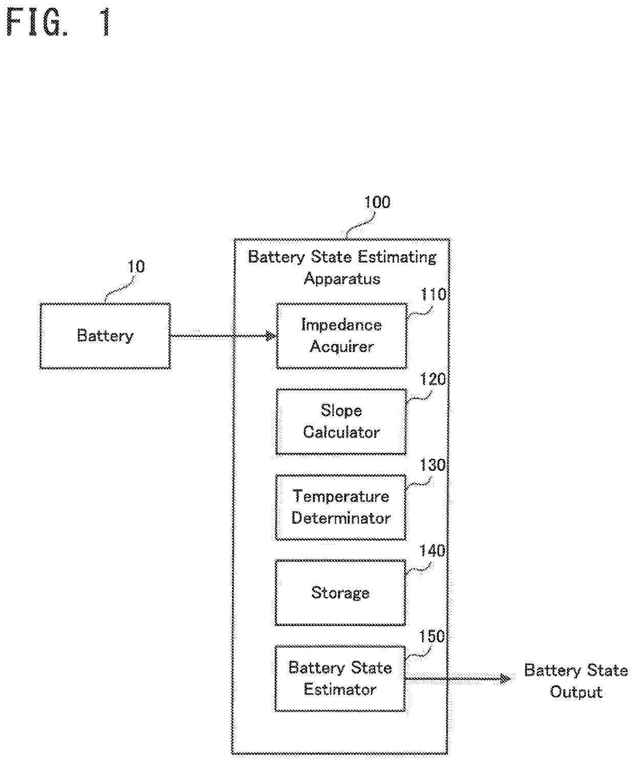
[0047]Firstly, a configuration of the battery state estimating apparatus 100 according to the first embodiment will be explained with reference to FIG. 1. FIG. 1 is a block diagram illustrating the configuration of the battery state estimating apparatus 100 according to the first embodiment.

[0048]As illustrated in FIG. 1, the battery state estimating apparatus 100 according to the first embodiment is an electronic unit electrically connected to a battery 10 of a vehicle, and is configured to estimate a SOC, which is a battery state of the battery 10. The battery 10 is a specific example of the “battery”, and is configured as a chargeable aqueous secondary battery, such as, for example, a lithi...

second embodiment

[0096]Next, a battery state estimating apparatus according to a second embodiment will be explained. The second embodiment is partially different from the first embodiment in operation, and the other part is substantially the same. Thus, hereinafter, a different part from that of the first embodiment explained above will be explained in detail, and an explanation of the same part will be omitted.

[0097]A specific flow of the operation of the battery state estimating apparatus 100 according to the second embodiment will be briefly explained with reference to FIG. 14. FIG. 14 is a flowchart illustrating a flow of the operation of the battery state estimating apparatus 100 according to the second embodiment. FIG. 14 carries the same reference numerals as those for the same steps illustrated in FIG. 13.

[0098]As illustrated in FIG. 14, in operation of the battery state estimating apparatus 100 according to the second embodiment, the impedance acquirer 110 firstly obtains the complex imped...

third embodiment

[0104]Next, a battery state estimating apparatus according to a third embodiment will be explained. The third embodiment is partially different from the first and second embodiments in operation, and the other part is substantially the same. Thus, hereinafter, a different part from those of the first and second embodiments explained above will be explained in detail, and an explanation of the same part will be omitted.

[0105]A specific flow of the operation of the battery state estimating apparatus 100 according to the third embodiment will be briefly explained with reference to FIG. 15. FIG. 15 is a flowchart illustrating a flow of the operation of the battery state estimating apparatus 100 according to the third embodiment. FIG. 15 carries the same reference numerals as those for the same steps illustrated in FIG. 13.

[0106]As illustrated in FIG. 15, in operation of the battery state estimating apparatus 100 according to the third embodiment, the impedance acquirer 110 firstly obtai...


PUM


Abstract

A battery state estimating apparatus is provided with: an acquirer configured to obtain complex impedances of a battery at a different temperatures; a calculator configured to calculate a slope of a first straight line or a slope of a second straight line as an impedance slope, wherein the first straight line connects values of the complex impedances at a first predetermined frequency, wherein the second straight line connects a convergence point and at least one of values of the plurality of complex impedances at a second predetermined frequency; and an estimator configured to estimate a battery state associated with the battery on the basis of the impedance slope and a relation stored in a storage, if it is determined by a determinator that a temperature of the battery is in a predetermined temperature area.

Description

CROSS-REFERENCE TO RELATED APPLICATIONS[0001]This application is based upon and claims the benefit of priority of the prior Japanese Patent Application No. 2017-056058, filed on Mar. 22, 2017, the entire contents of which are incorporated herein by reference.BACKGROUND1. Technical Field[0002]Embodiments of the present disclosure relate to a battery state estimating apparatus configured to estimate a state of a battery mounted on a vehicle or the like.2. Description of the Related Art[0003]For this of apparatus, there is known an apparatus configured to estimate a charge amount, a degradation or deterioration state, or the like of a battery by analyzing an impedance of the battery. For example, in International Publication No. WO2013 / 114669 (Patent Literature 1), there is proposed a technique / technology in which the charge amount of the battery is detected from an angle of a slope of a straight line connecting two or more complex impedances with different frequencies. Moreover, in In...

Claims


Application Information

Patent Timeline
Patent Type & Authority Patents(United States)
IPC IPC(8): G01R31/389G01R31/367G01R31/374G01R31/392G01R31/387
CPCG01R31/392G01R31/389G01R31/387G01R31/374G01R31/367
Inventor OGUMA, YASUMASAOSAKA, TETSUYAYOKOSHIMA, TOKIHIKOTSUDA, SHINGOUTSUMI, KAZUAKIMUKOYAMA, DAIKICHI
Owner TOYOTA JIDOSHA KK
Features
  • R&D
  • Intellectual Property
  • Life Sciences
  • Materials
  • Tech Scout
  • Unparalleled Data Quality
  • Higher Quality Content
  • 60% Fewer Hallucinations
Learn More