
Self-powered computing buoy

a self-powered, computing buoy technology, applied in special-purpose vessels, vessel construction, instruments, etc., can solve the problems of large-scale computing, computer heat generation, electrical power in order to operate, etc., to achieve low maintenance, reduce power consumption, and reduce the effect of deploymen

Active Publication Date: 2020-06-02
LONE GULL HLDG LTD
View PDF17 Cites 2 Cited by
  • Summary
  • Abstract
  • Description
  • Claims
  • Application Information

AI Technical Summary

Benefits of technology

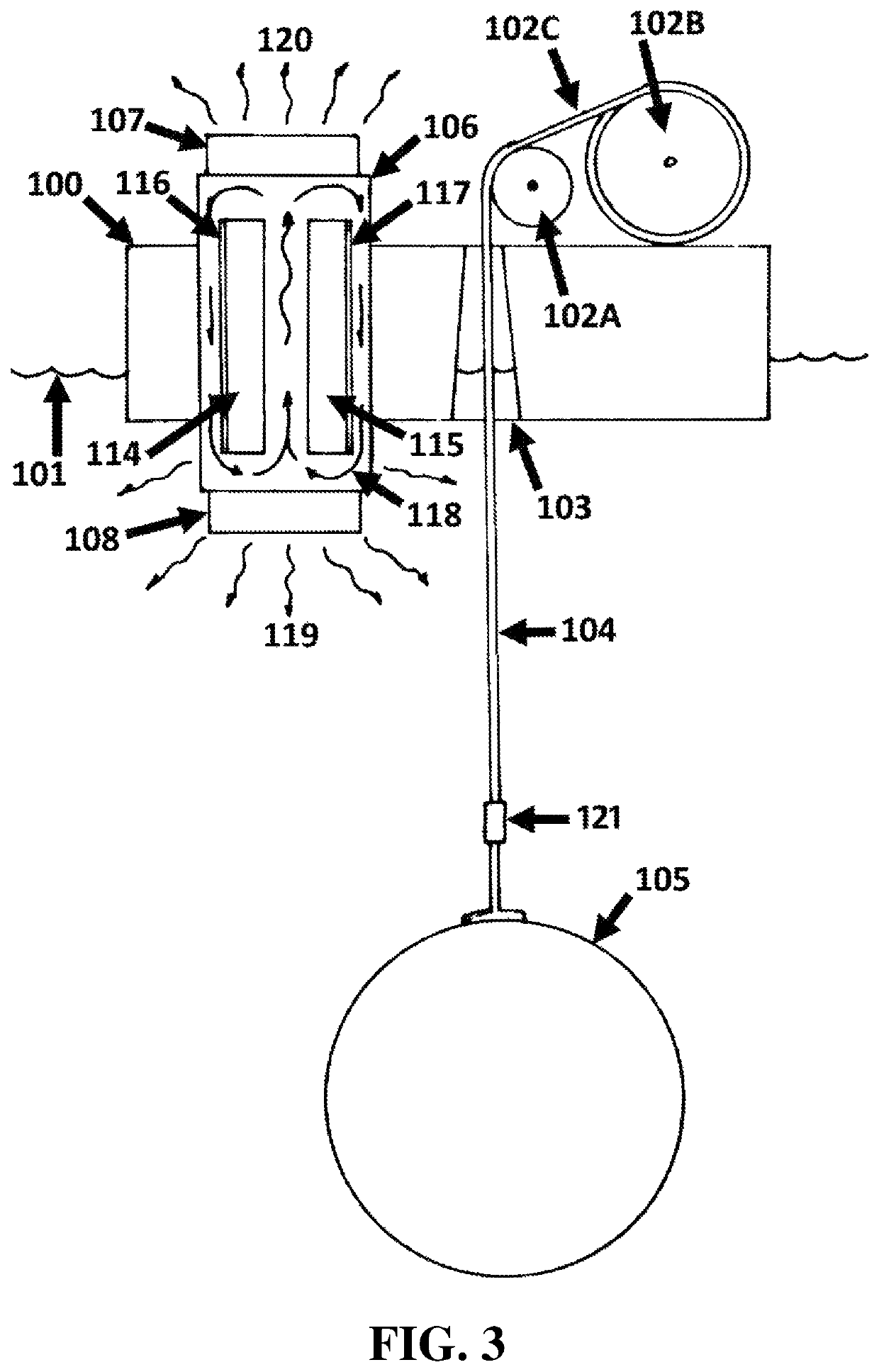
[0004]Disclosed is a novel type of computing apparatus which is integrated within a buoy that obtains the energy required to power its computing operations from waves that travel across the surface of the body of water on which the buoy floats. Additionally, these self-powered computing buoys employ novel designs to utilize their close proximity to a body of water and / or to strong ocean winds to significantly lower the cost and complexity of cooling their computing circuits. Computing tasks of an arbitrary nature are supported, as is the incorporation and / or utilization of computing circuits specialized for the execution of specific types of computing tasks, such as the “mining” of cryptocurrencies such as Bitcoin. And, each buoy's receipt of a computational task, and its return of a computational result, may be accomplished through the transmission of data across satellite links, fiber optic cables, LAN cables, radio, modulated light, microwaves, and / or any other channel, link, connection, and / or network. Systems and methods are disclosed for parallelizing computationally intensive tasks across multiple buoys. Multi-purpose buoys, and methods for employing the same, are disclosed, wherein the electrical energy produced by a buoy is normally directed to the buoy's computing circuits to carry out computationally intensive tasks, but can intermittently be redirected to serve sporadic purposes such as the electrical charging of nearby ocean-going and airborne drones. Also disclosed is a “farm” or array configuration wherein multiple mutually inter-tethered buoys share power for computationally intensive tasks across a common power bus, reducing the need for the buffering or storage of said power.
[0009]While the current disclosure does not preclude the anchoring of the disclosed devices, it nevertheless allows wave energy devices to make good use of the electrical power that they generate without being anchored and / or moored to the seafloor, and without an electrical cable to shore.
[0014]Also, because the computers stored and operated within the devices of the present disclosure are located on buoys that are floating on a body of water (e.g., on the sea far from shore), they provide significant computing power without requiring a concomitant dedication of a significant area of land. This potentially frees land that might otherwise have been used to house such computing clusters, so that it might instead be used for farming, homes, parks, etc.
[0019]Many of the aforementioned applications, however, consume power only sporadically, and are therefore unlikely to be economical. It is unlikely to be economical, for instance, to deploy a dedicated wave energy converter for the charging of drones. However, such a deployment can become economical if there is a use to which electrical power can be put during normal operation, between such sporadic uses. The performance of computationally intensive tasks using computational circuits is one of the simplest, most low-capital-cost and low-maintenance ways of using electrical power.

Problems solved by technology

Large-scale computing currently has at least two significant limitations and / or drawbacks.
The first obstacle is that computers require electrical power in order to operate and perform their calculations.
The second obstacle to large scale computing is that computers generate heat.
The heat generated by computers can raise the temperatures of computers to levels that can cause those computers to fail, especially when the computers are located in close proximity to one another.
This cooling, e.g. through air conditioners and fans, consumes significant electrical power over and above the electrical power used to energize the computers.

Method used


Image

  • Self-powered computing buoy
  • Self-powered computing buoy
  • Self-powered computing buoy

Examples


embodiment 100

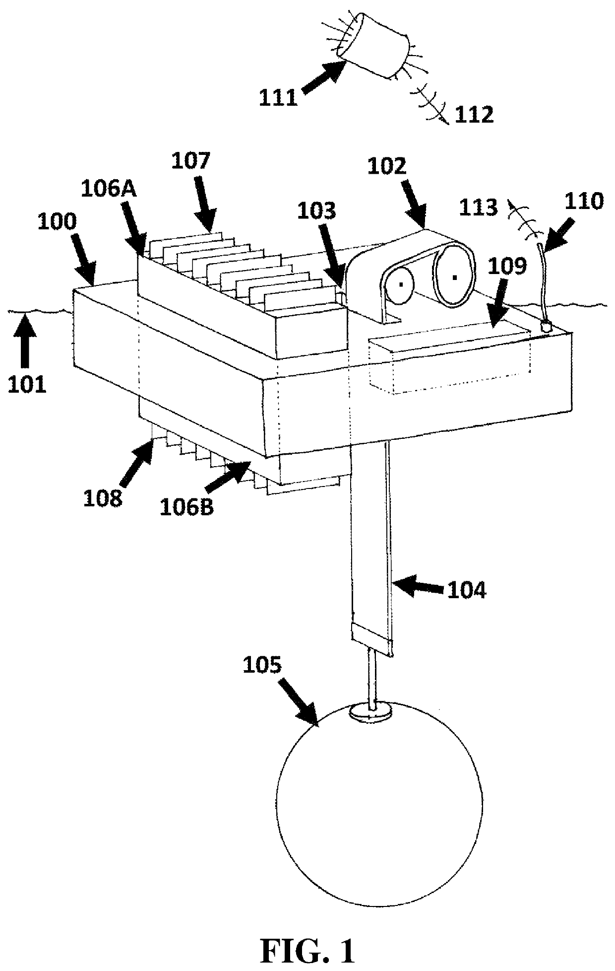
[0192]The illustrated embodiment 100 receives tasks, programs, data, messages, signals, information, and / or digital values, emitted 112, issued, and / or transmitted, from at least one satellite 111, at least in part, through antenna 110, the data transmitted by the satellite 111 having, at least in part, originated from a remote computer and / or server.

[0193]The illustrated embodiment 100 transmits 113, communicates, emits, and / or issues, data, task results, messages, signals, information, status updates, and / or digital values, at least in part, from antenna 110, which are subsequently received, at least in part, by satellite 111, which may then transmit that received data to a remote computer and / or server.

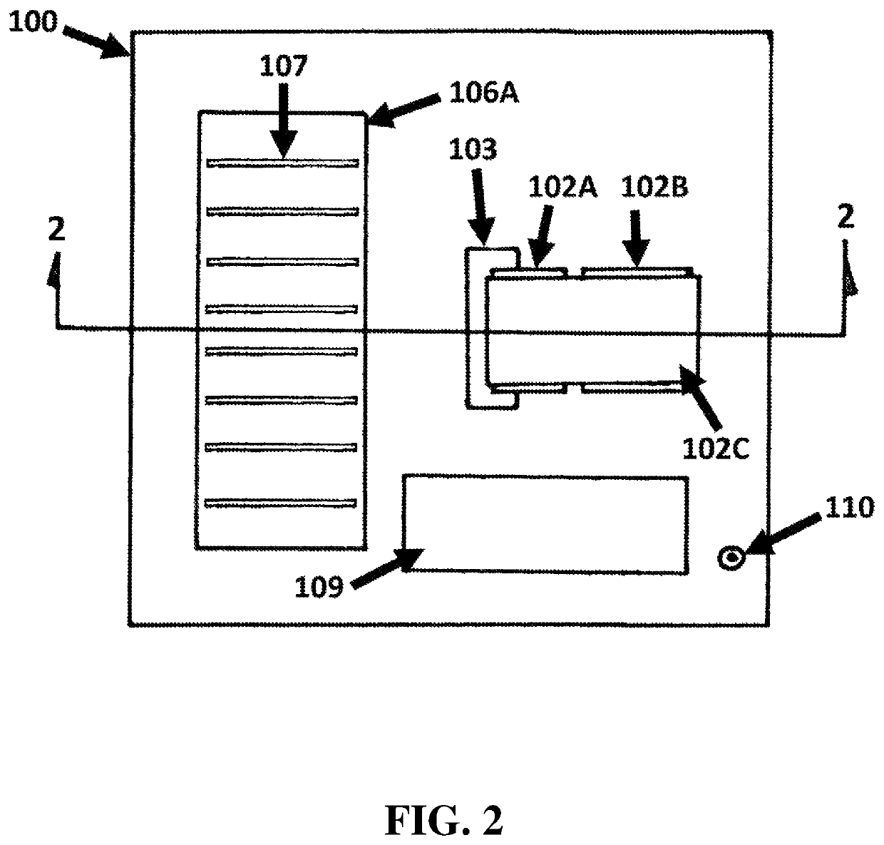
[0194]FIG. 2 shows a top-down view of the embodiment of FIG. 1. A buoy 100 floats adjacent to the surface of a body of water. Attached to, mounted on, and / or incorporated within, the buoy 100 is a power take-off (PTO) 102, and / or electrical power-generation assembly. The PTO includ...

embodiment 130

[0205]The embodiment 130 incorporates a rigid sail 140 that is able to impart thrust to the device when driven by wind. The amount of thrust being adjustable and / or able to be optimized through the rotation of the sail to an optimal angle with respect to the wind direction. An antenna 144 mounted on, and / or affixed to, the top of the rigid sail 140 allows the device to send and receive electronic, and / or electromagnetic, transmissions (e.g. radio).

[0206]FIG. 6 shows a side view of the embodiment of FIG. 4. A buoy 130 floats adjacent to the surface 131 of a body of water. Attached to, mounted on, and / or incorporated within, the buoy 130 is a plurality of power take-offs (PTOs), e.g. 132, and / or electrical power-generation assemblies. PTO-specific cables, e.g. 133, chains, ropes, linkages, and / or flexible connectors, connect each respective PTO to the approximate center of a submerged inertial mass 134. The cables pass through a hole 135 and / or aperture in a top surface of the inertia...

embodiment 375

[0288]FIG. 22 illustrates the processes and / or events that are characteristic of some embodiments of the present invention. A satellite 370 transmits 371 a data packet to a transceiver 372, and / or data communication system, on an embodiment of the present invention. The embodiment 373 receives, validates, and possibly decrypts, the “task data” encoded within the data packet. If the task data 374 specifies a new program and / or task, and any related data, then 374 the embodiment 375 adds the new task and its related data (if any) to its task queue 376.

[0289]When 377 there is an available CPU, computer, and / or sufficient available computing resources, then 378 a pending task is identified and / or selected, and its execution is started on the available CPU 380. A “timeout” value 379 is associated with the selected pending task in the task queue 376. This timeout value represents a future time after which it will be reasonable for the embodiment to assume that the task's execution has fai...


PUM


Abstract

A computing apparatus that is integrated within a flotation module, the system obtaining the energy required to power its computing operations from waves that travel across the surface of a body of water on which the flotation module sets. Additionally, the self-powered computing apparatus employs novel designs to utilize its close proximity to the body of water and / or to strong ocean winds to significantly lower the cost and complexity of cooling their computing circuits.

Description

CROSS-REFERENCES TO RELATED APPLICATIONS[0001]This application claims priority to U.S. Provisional Application Nos. 62 / 533,058 filed Jul. 16, 2017; 62 / 622,879 filed Jan. 27, 2018; 62 / 688,685 filed Jun. 22, 2018; and 62 / 696,740 filed Jul. 11, 2018, the contents of which are incorporated herein by reference in their entirety.BACKGROUND[0002]Large-scale computing currently has at least two significant limitations and / or drawbacks. The first obstacle is that computers require electrical power in order to operate and perform their calculations. Some of the power energizes the CPUs while remaining power energizes the random-access memory, shared and / or more persistent memory (e.g. hard disks), switches, routers, and other equipment supporting network connections between computers. As society's reliance on computers and computing increases, the portion of the world's energy budget that is consumed by computers and computing also increases. By some estimates, computers and computing current...

Claims


Application Information

Patent Timeline
Patent Type & Authority Patents(United States)
IPC IPC(8): B63B22/18H04L9/32B63H21/00B63B39/06F03B13/24F03B13/14F03B13/18F03B13/20G09C1/00H04L9/06F03B13/16B63B22/00
CPCF03B13/183F03B13/24G09C1/00F03B13/20H04L9/3239B63H21/00F03B13/142B63B22/18B63B39/06H04L9/0637F03B13/1885F05B2240/40F05B2240/931F03B13/145F05B2260/42F05B2260/20F03B13/16H04L2209/38B63B2022/006F03B13/189F05B2260/2241Y02T50/60Y04S40/20B63J2003/046B63B2035/4466B63B2035/006B63B1/048B63B2001/044Y02T70/00H04L9/50F03B13/22
Inventor SHELDON-COULSON, GARTH ALEXANDERMOFFAT, BRIAN LEE
Owner LONE GULL HLDG LTD
Learn More