
Method and apparatus for the insertion of weft threads

a technology for weaving machines and weft threads, applied in weaving, looms, textiles and papermaking, etc., can solve the problems of additional cost and complexity, complicated threading in of individual weft threads into associated nozzles, and damage to weft threads by retaining air flow, so as to simplify the threading in of weft threads

Inactive Publication Date: 2010-07-06
ITEMA (SWITZERLAND) LTD
View PDF53 Cites 0 Cited by
  • Summary
  • Abstract
  • Description
  • Claims
  • Application Information

AI Technical Summary

Benefits of technology

[0005]An object of the present invention is to make available an apparatus for the insertion of weft threads in a weaving machine which has a lower cost and complexity in comparison with conventional apparatuses as well as a method which simplifies the threading of a weft thread into a nozzle. A further object of the invention consists in making available a weaving machine with an apparatus of this kind for the insertion of weft threads or for carrying out a method of this kind.
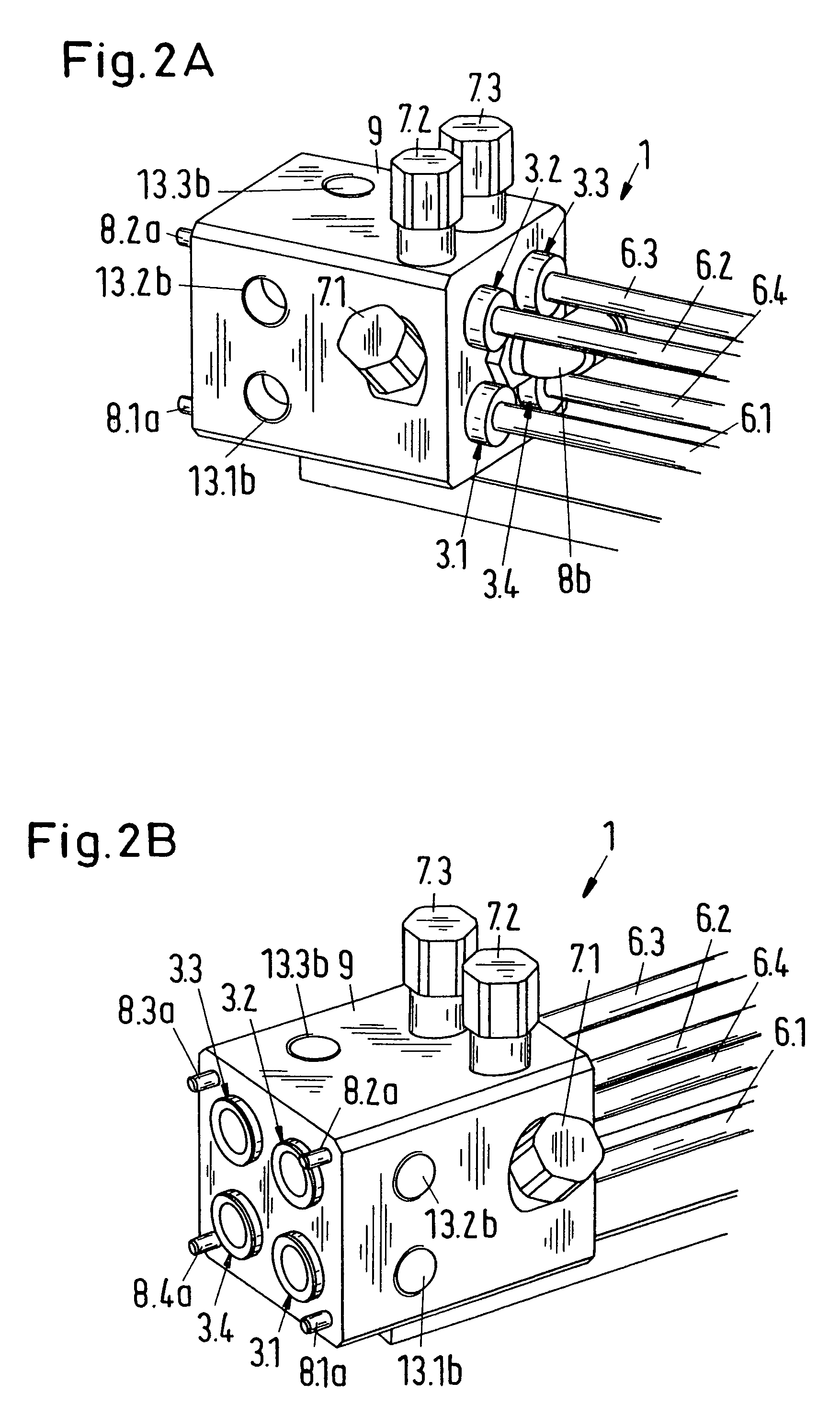
[0014]The apparatus in accordance with the invention and the method in accordance with the invention for the insertion of weft threads have the advantage that the threading in of a weft thread is simplified by the control valve which is attached to the nozzle holder or nozzle or clamping device, for example in that the control valve is actuated by hand during the threading in. A further advantage is that when the apparatus comprises a plurality of nozzles, the apparatus can be supplied via a single supply line with the medium which is used for charging the clamping devices and / or for the threading in.

Problems solved by technology

In contrast, when the weaving machine is stopped, the weft threads are held firmly by clamping devices which are arranged in the mixing tube of the nozzles; and the retaining air flow is interrupted since there is the danger when the machine stands still for a longer period of time that the weft threads will be damaged by the retaining air flow.
The clamping devices have the disadvantage however that they complicate the threading in of individual weft threads into the associated nozzles, since the clamping devices must be opened individually via the weaving machine control system for the threading in.
The individual control of the clamping devices is connected with additional cost and complexity since in addition to one control valve per clamping device a supply line for the compressed air is also needed.

Method used


Image

  • Method and apparatus for the insertion of weft threads
  • Method and apparatus for the insertion of weft threads
  • Method and apparatus for the insertion of weft threads

Examples


Embodiment Construction

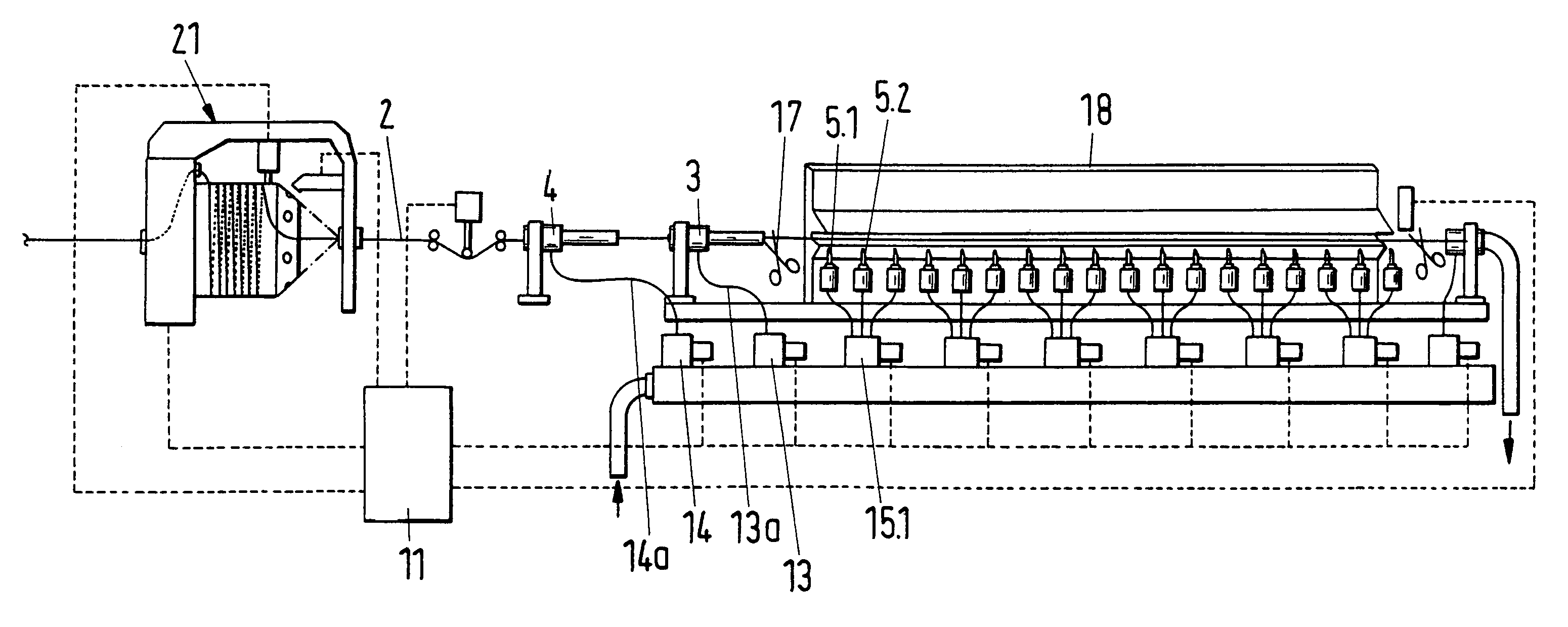
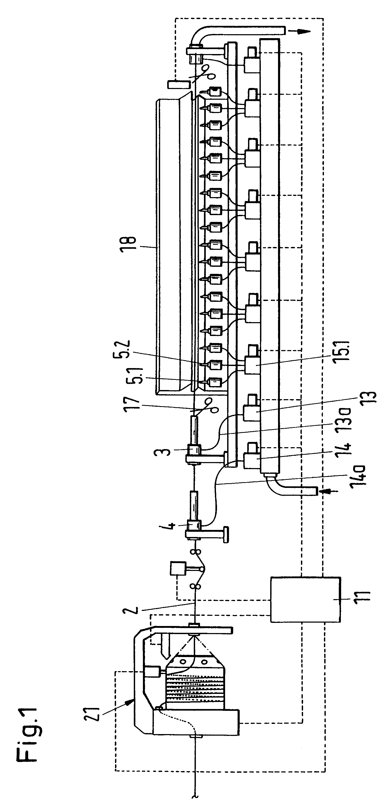
[0024]In the view of a conventional air jet weaving machine which is shown in FIG. 1 the weaving machine comprises a thread storage 21 for the provision of a weft thread 2, a plurality of air nozzles 3, 4, 5.1, 5.2, a control system 11 which is connected to control valves 13, 14, 15.1, and supply lines 13, 14 which connect the control valves to the corresponding air nozzles in order to charge the air nozzles with a medium, for example with compressed air, for the insertion of the weft thread. The air nozzles comprise for example a tandem nozzle 4 and a main nozzle 3 in order to accelerate the weft thread 2 which is drawn off from the thread storage 21 and to blow it into a shed, and relay nozzles 5.1, 5.2 in order to transport the weft thread further in the shed. In place of the tandem and main nozzles 3, 4 it is also possible to provide only a single main nozzle 3 in order to accelerate the weft thread or, depending on the application, a large number of main nozzles 3 in order to a...


PUM


Abstract

An apparatus (1) for the insertion of weft threads in a weaving machine is presented. The apparatus includes a nozzle holder (9) and, secured thereto, at least one nozzle (3) with a mixing tube (6) for the insertion of a weft thread (2) as well as a clamping device (7) which can be charged with a medium in order to firmly clamp a weft thread which is introduced into the nozzle. In addition the apparatus (1) contains at least one control valve (8) which is arranged at or in the nozzle holder (9) or nozzle (3) in order to control the clamping device (7).

Description

BACKGROUND OF THE INVENTION[0001]The invention relates to an apparatus for the insertion of weft threads in a weaving machine and to a method for the insertion of weft threads in a weaving machine as well as to a weaving machine with an apparatus of this kind and for carrying out a method of this kind.[0002]In DE 32 00 638 A1 an air jet weaving machine is described which comprises a nozzle with a mixing tube for the insertion of weft threads and a reed for beating up the latter. A thread clamp is arranged in the mixing tube of the nozzle in order to firmly clamp the weft thread during the severing or during the standstill of the weaving machine and thereby to prevent a jumping back of the weft thread in the nozzle. This arrangement of the thread clamp permits arranging the mixing tube close to a weft thread guiding passage which is formed in the reed, so that during the insertion the deviation in the desired position of the weft thread between the mixing tube and the weft thread gui...

Claims


Application Information

Patent Timeline
IPC IPC(8): D03D47/30D03D23/00
CPCD03D47/3013D03D47/3053D03D47/306
Inventor JENNE, CHRISTOPH
Owner ITEMA (SWITZERLAND) LTD
Learn More