Load distributor for a sternum closure device and tool for cutting the load distributor

a technology of sternum closure device and distributor, which is applied in the direction of osteosynthesis device, internal osteosynthesis, internal osteosynthesis, etc., can solve problems such as damage to the bone, and achieve the effect of limiting unnecessary damage to the sternum bone and reliable operation

Active Publication Date: 2020-07-21
STRYKER EURO OPERATIONS HLDG LLC
View PDF10 Cites 1 Cited by
  • Summary
  • Abstract
  • Description
  • Claims
  • Application Information

AI Technical Summary

Benefits of technology

[0010]There is a need for a sternum closure device and associated parts which can be reliably operated and limit unnecessary damage to the sternum bone.
[0023]One or both of the end segments of the segment row may have pointed shape (e.g., a V-shape) at their side facing away from the adjacent segment. The pointed shape may facilitate the placement of the sternum closure device around sternum bone.
[0029]The longitudinal extension of the tool may correspond to the extension of the load distributor when arranged between the two jaws for cutting. Upon cutting the load distributor, the wire may or may not be attached thereto. In the second position, the jaws may leave a clearance hole. The clearance hole may be dimensioned to essentially correspond to or slightly exceed the first cross-sectional dimension (e.g., a diameter of the wire). In such a case, the clearance hole may prevent a cutting or damaging of the wire upon cutting the load distributor (i.e., may enable a skinning of the wire in relation to a portion of the load distributor).

Problems solved by technology

The protector pads avoid that the wire cuts into the bone surface when tensioning it, thus causing damage to the bone.

Method used


Image

  • Load distributor for a sternum closure device and tool for cutting the load distributor
  • Load distributor for a sternum closure device and tool for cutting the load distributor
  • Load distributor for a sternum closure device and tool for cutting the load distributor

Examples


first embodiment

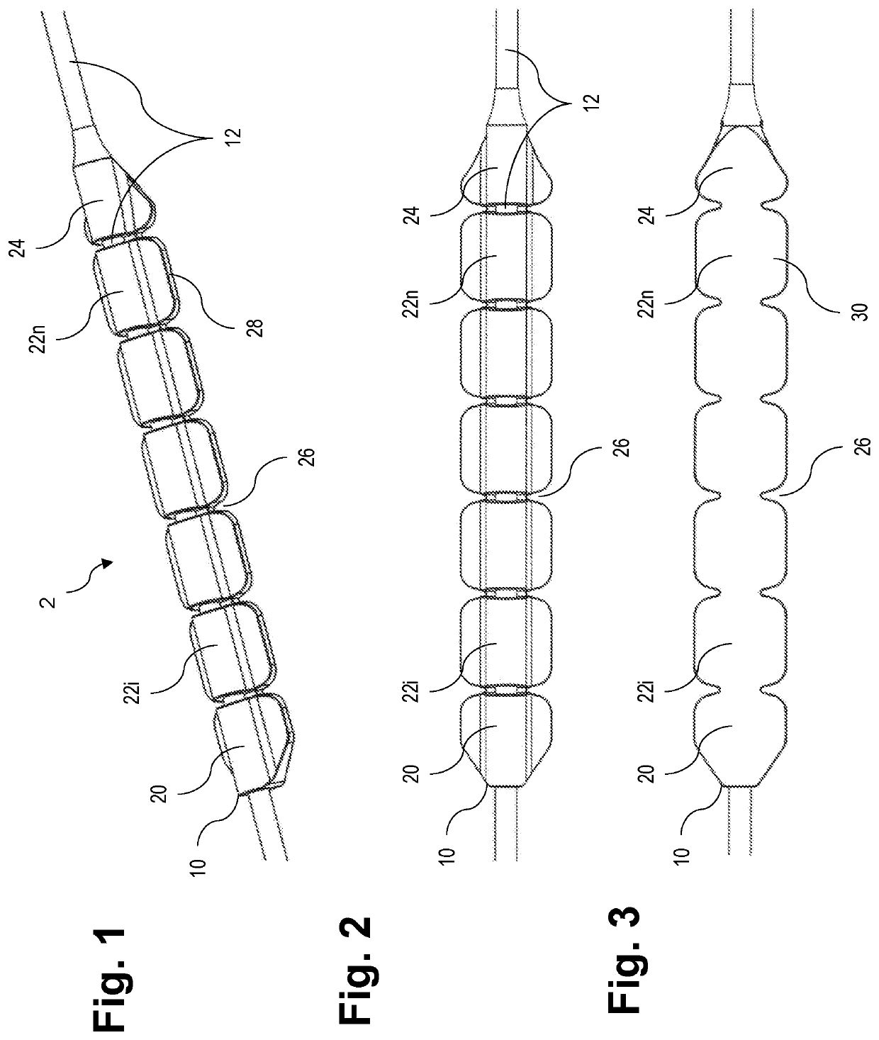
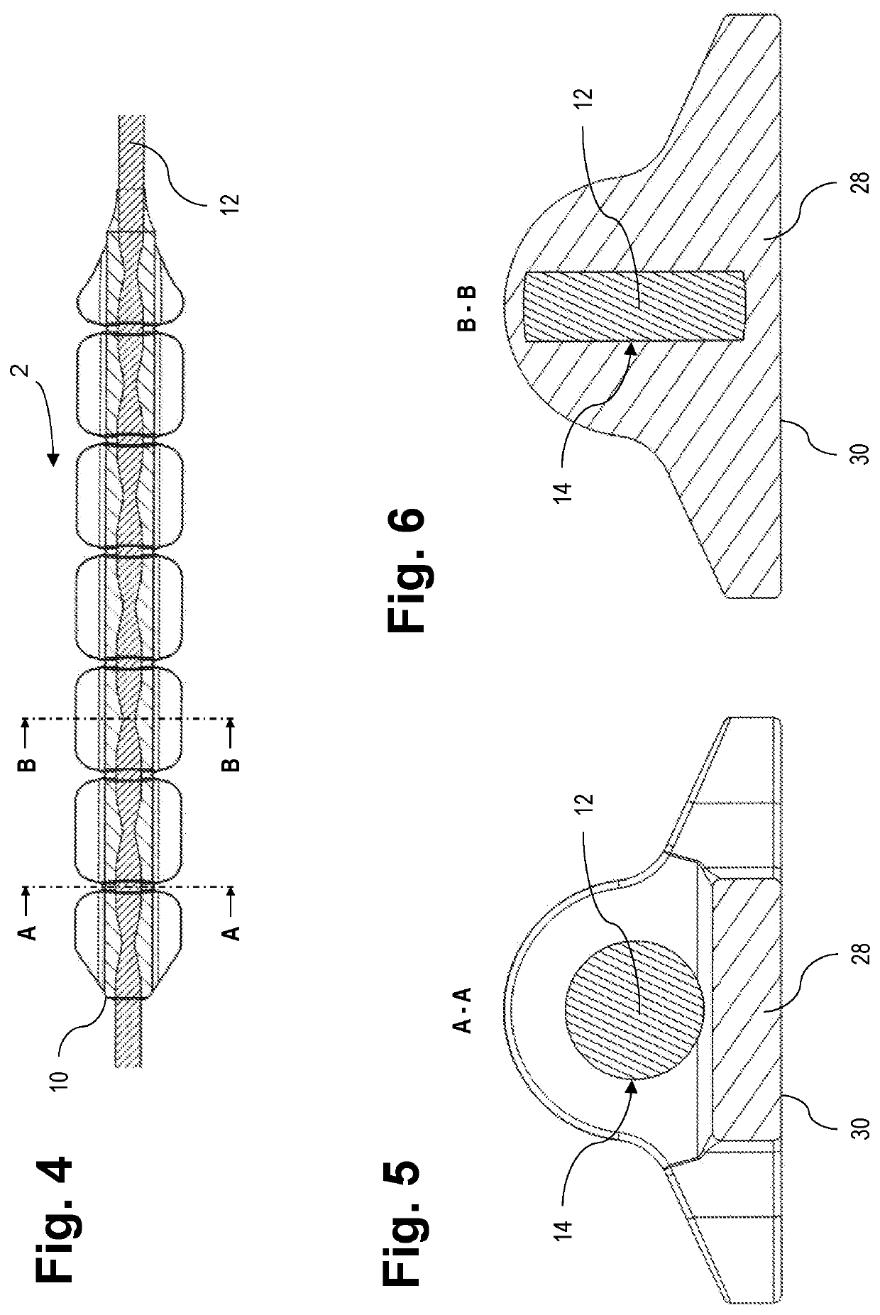
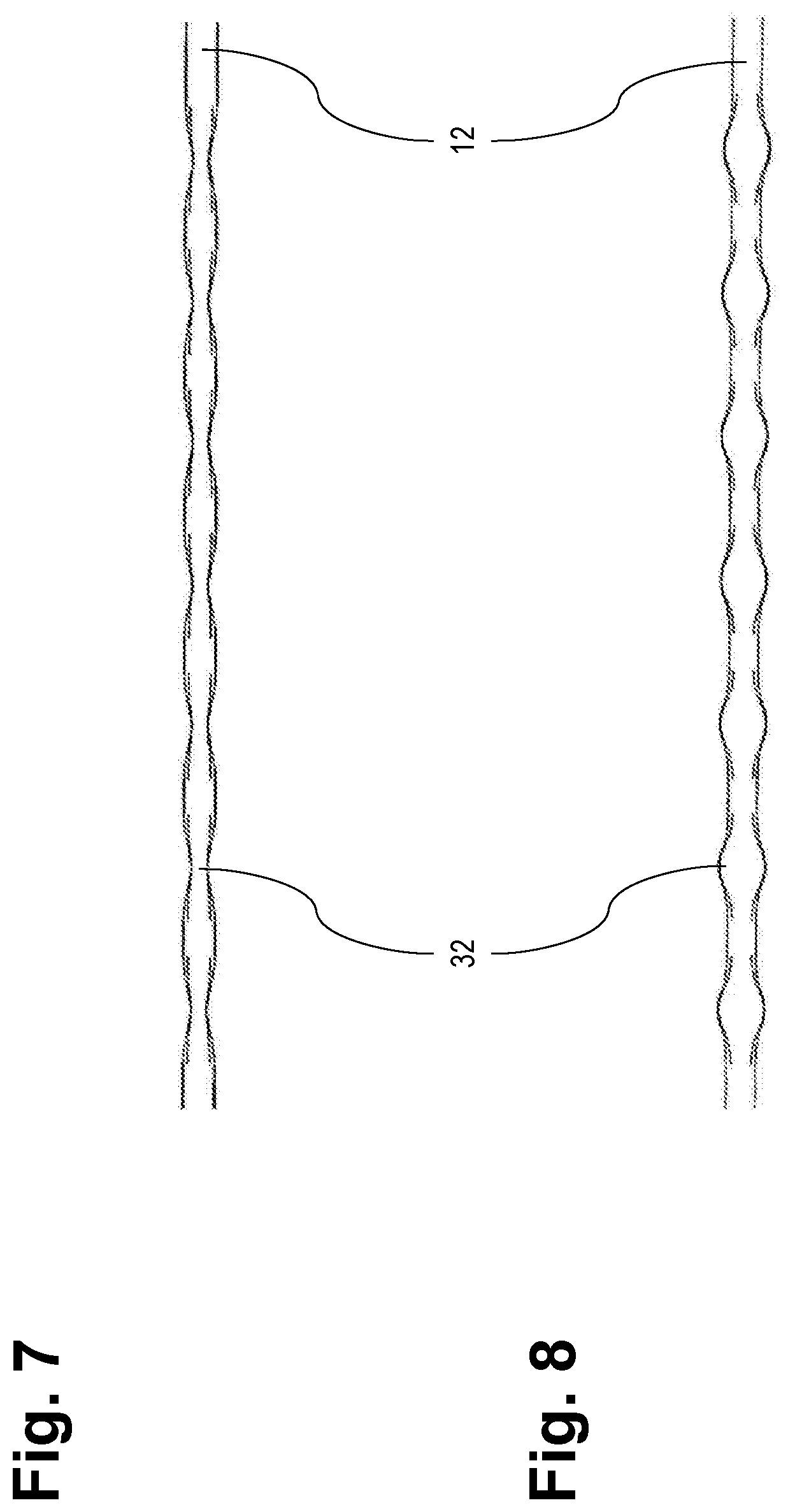
[0056]The wire receiving section 14 of the first embodiment in FIGS. 1 to 6 basically corresponds to the one shown by a side cross-section of a load distributor 100 shown in FIG. 10 and described further below. However, in FIG. 1, the wire receiving section 14 is configured to be attached to the wire 12 by being molded over the wire 12. In order to improve the engagement by the wire receiving section 14 with the wire 12, the wire 12 may be provided with a surface feature such as an increased surface roughness, protrusions, indentations (see FIGS. 7 and 8) or the like.

[0057]The load distributor 10 has a load distributing section 28 configured to extend between a sternum bone and the wire 12. The load distributing section 28 has a substantially flat bone-contacting region 30 (see FIG. 3).

[0058]In one variant, the load distributing section 28 has a substantially rectangular shape with two straight sides parallel to an extension of the wire 12. In the present embodiments, the load distr...

second embodiment

[0070]FIG. 9 shows a perspective top view of a crimpable load distributor 100 according to a This load distributor 100 has a crimpable sleeve 34 substantially defining the first cross-sectional dimension. The sleeve 34 is arranged in between two equally long portions of a segment row (as explained above with reference to FIGS. 1 to 8). The sleeve 34 is overmolded by the segment rows at their respective innermost segments. These overmolded segments are tapered towards each other towards the sleeve 34. The particular shape of the sleeve 34 and interconnection with the respective segments of the segment row will become apparent from the following description of FIG. 10 in conjunction with FIG. 9.

[0071]FIG. 10 shows a longitudinal side cross-section of the sleeve 34 and load distributor 100 in FIG. 9. The load distributor 10 discussed above in connection with FIGS. 1 to 8 has a similar cross-sectional appearance.

[0072]The sleeve 34 in the load distributor 100 illustrated in FIGS. 9 and...

third embodiment

[0075]FIG. 14 shows a perspective view of a tool 50 according to a The tool 50 has a pair of riffled handles 52, a pivot 54, and a pair of L-shaped jaws 56, 58. The tool 50 will be used by surgical personal to cut the load distributor 10, 100 (e.g., to “skin” on or more load distributor segments from the wire 12) and / or to crimp the sleeve 34 onto the wire 12.

[0076]FIG. 15 shows an enlarged perspective view of a jaw section of the tool 50 in FIG. 14. In this view it is visible that the jaw section has a cutting and skinning section 60 and a crimping section 62. The crimping section 62 has a symmetrical recess 68a on one jaw 56 and a complementary protrusion 68b on the other jaw 58. The recess 68a has tapered end parts 70 such that it corresponds to the outer shape of the sleeve 34 and the tapered segments of the load distributor 100 closest to the sleeve 34 (see, e.g., FIGS. 1, 4, and 9).

[0077]The pair of jaws 56, 58 is movable between a first load distributor receiving position an...


PUM


Abstract

A load distributor for a sternum closure device comprises a wire receiving section configured to be attached to a wire of the sternum closure device, and a load distributing section. A tool for cutting the load distributor comprises a pair of jaws movable between a load distributor receiving position and a cutting position, wherein at least one of the jaws has substantially V-shaped cutting edges tapered towards the other jaw in an angle to the longitudinal extension of the tool.

Description

CROSS-REFERENCE TO RELATED APPLICATIONS[0001]The present application claims the benefit of European Patent Application No. 16000665.6, filed Mar. 18, 2016, the disclosure of which is hereby incorporated herein by reference.BACKGROUND OF THE INVENTION[0002]The present disclosure generally relates to surgical devices. In particular, a load distributor for a sternum closure device, a sternum closure device comprising the load distributor, a tool for cutting the load distributor, and a sternum closure system comprising the load distributor and the tool are described.[0003]To promote the healing process of fragmented or cut bone, it has been known to exert an external force on bone parts by tightly clamping them together. To this end, flexible elongated members such as wires can be used which are tensioned around the bone parts.[0004]For example, prior to heart surgery, the sternum bone is often cut into two halves by means of a longitudinal section to obtain access to the heart. The ste...

Claims


Application Information

Patent Timeline
Patent Type & Authority Patents(United States)
IPC IPC(8): A61B17/82A61B17/88
CPCA61B17/823A61B17/8863A61B17/8861
Inventor BEYERSDORF, FRIEDHELMKNOEPFLE, CHRISTIANGREINER, KARLSCHMUCK, MANFRED
Owner STRYKER EURO OPERATIONS HLDG LLC
Why Eureka
Try Eureka