Electric power supply system for a hall effect electric thruster

a technology of electric power supply system and hall-effect electric thruster, which is applied in the field of space propulsion, can solve the problems of increasing the cost, volume and mass of increasing the cost, volume and mass of the hall-effect electric thruster and its power processing units, and maintaining the complex power supply of the igniter, so as to achieve simple and economical solutions

Active Publication Date: 2020-07-21
AIRBUS DEFENCE & SPACE
View PDF4 Cites 1 Cited by
  • Summary
  • Abstract
  • Description
  • Claims
  • Application Information

AI Technical Summary

Benefits of technology

[0028]This invention aims to remedy all or a part of the limitations of the solutions offered by the prior art, particularly those disclosed hereinabove, by providing a simple and economical solution while guaranteeing the reliability of the ignition of the Hall-effect electric thruster.
[0036]Such an electric power supply system provides for a simpler powering of the igniter by means of a passive electrical circuit comprising solely of the standard passive components.
[0037]The voltage generated, in the form of pulses, between the igniter and the cathode allows the reliability of the ignition of the Hall-effect electric thruster to be favourably improved.

Problems solved by technology

The management of the power supply of the igniter 52 proves to be very complex (multiple sources of power, electronic control sensor, switching from one mode of operation to the other), which contributes to increase in the cost, volume and mass of the Hall-effect electric thruster and its power processing units (PPU).
In addition, the number and complexity of electronic devices affect the reliability of said Hall-effect electric thruster, which necessitates over-sizing and / or redundancies, thus raising the cost, volume and mass even more.
However, the power supply of the igniter remains very complex.
The power supply system also proves to be complex and costly, particularly due to the use of an inductance.

Method used


Image

  • Electric power supply system for a hall effect electric thruster
  • Electric power supply system for a hall effect electric thruster
  • Electric power supply system for a hall effect electric thruster

Examples


Embodiment Construction

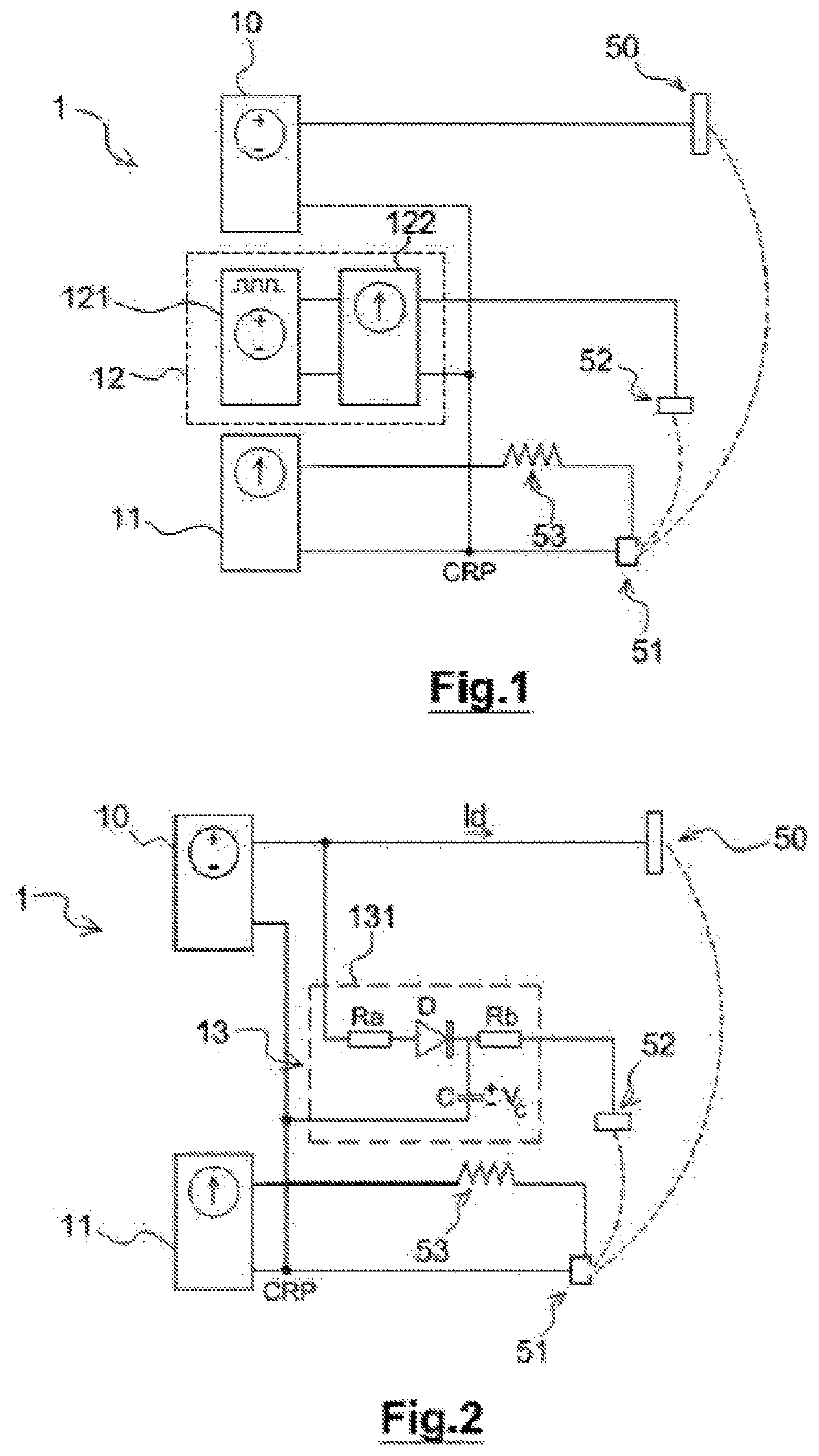
[0061]This invention relates to an electric power supply system 1 of a Hall-effect electric thruster 1.

[0062]A Hall-effect thruster usually comprises, on the one hand, a discharge channel to which an anode 50 is connected and, on the other hand, a cathode assembly situated near the outlet of the discharge channel. The cathode assembly comprises a cathode 51 and a heater 53 situated close to the cathode 51 and meant to heat said cathode to allow it to emit electrons. A magnetic circuit surrounds the discharge channel and creates a radial magnetic field within the discharge channel. A propellant gas, e.g. xenon, is injected at the rear of the discharge channel and in the cathode. The propellant gas is ionised in the discharge channel by collision with the electrons emitted by cathode 51. The ionisation of the propellant gas generates plasma. The ions produced are accelerated and ejected at very high speed (15 to 25 km / s) by an axial electric field created between the anode and the cat...


PUM


Abstract

An electric power supply system for a Hall effect electric thruster. The Hall effect electric thruster includes an anode, a cathode, a heater for the cathode and an igniter. The electric power supply system includes a first power supply source to power the anode, a second power supply source to power the heater and a power supply unit to electrically supply the igniter. The power supply unit includes a third power supply source and a passive electric circuit. The third power supply source powers the passive electric circuit and is configured to generate a voltage in the form of at least one pulse.

Description

RELATED APPLICATIONS[0001]This application is a § 371 application of PCT / EP2017 / 066980 filed Jul. 6, 2017, which claims priority from French Patent Application No. 16 56532 filed Jul. 7, 2016, each of which is incorporated herein by reference in its entirety.FIELD OF THE INVENTION[0002]This invention belongs to the space propulsion domain. More specifically, this invention pertains to a Hall-effect electric thruster.[0003]This invention mainly pertains to an electric power supply system for a Hall-effect electric thruster.BACKGROUND OF THE INVENTION[0004]The working of a Hall-effect electric thruster and the role of its various constituent elements, namely an anode, a cathode, a magnetic circuit, and a heater of the cathode, are properly known to the person skilled in the art. An example that may be cited is “Fundamentals of Electric Propulsion: Ion and Hall Thrusters”, Dan M. Goebel and Ira Katz, JPL Space Science and Technology Series, March 2008. They are only briefly recalled he...

Claims


Application Information

Patent Timeline
Patent Type & Authority Patents(United States)
IPC IPC(8): F03H1/00H03K3/59
CPCF03H1/0018F03H1/0075H03K3/59
Inventor BROTONS, CYRILLOUBERE, DIMITRYSCREMIN, GUILLAUMEGUILHEM-DUCLEON, MATTHIAS
Owner AIRBUS DEFENCE & SPACE
Why Eureka
Try Eureka