
Loop antenna and design method for loop antenna

a loop antenna and loop antenna technology, applied in the field of loop antennas, can solve the problems of large power consumption, large increase in wireless coverage, and drawbacks of sharp distance decay property of magnetic field, and achieve the effect of large magnetic field

Active Publication Date: 2020-07-21
NIPPON TELEGRAPH & TELEPHONE CORP
View PDF20 Cites 0 Cited by
  • Summary
  • Abstract
  • Description
  • Claims
  • Application Information

AI Technical Summary

Benefits of technology

[0014]According to the present invention, it is possible to obtain a relatively large magnetic field even if a capacitance value of a capacitor attached to an antenna does not completely match an optimal value.

Problems solved by technology

The sharp distance decay property of the magnetic field is a drawback from the viewpoint of expanding the wireless coverage.
When expanding the wireless coverage in the wireless system using the magnetic field, a large current needs to be applied to the antenna, which may lead to a significant increase in power consumption.

Method used


Image

  • Loop antenna and design method for loop antenna
  • Loop antenna and design method for loop antenna
  • Loop antenna and design method for loop antenna

Examples


Embodiment Construction

[0022]An embodiment of the present invention will be described below with reference to the drawings.

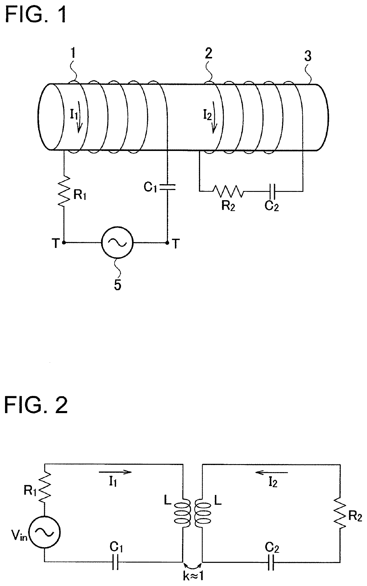
[0023]FIG. 1 is a diagram showing a configuration of a loop antenna of this embodiment.

[0024]The loop antenna shown in FIG. 1 is a resonant-type loop antenna which includes a main loop 1 and an amplification loop 2.

[0025]The main loop 1 is a coil wound around a bar-shaped rod 3 made of either a magnetic body or an insulating body. The number of turns in the main loop 1 is at least 1 and the number of turns is 5 in the example of FIG. 1. A resistor R1 and a capacitor C1 are connected in series to the main loop 1. The main loop 1 is an open loop that includes terminals T and T for establishing connection to a signal source 5 or a reception circuit (not shown).

[0026]The amplification loop 2 is a coil wound around the rod 3 at a position away from the main loop 1. The number of turns in the amplification loop 2 is at least 1 and the number of turns is 5 in the example of FIG. 1. A resisto...


PUM


Abstract

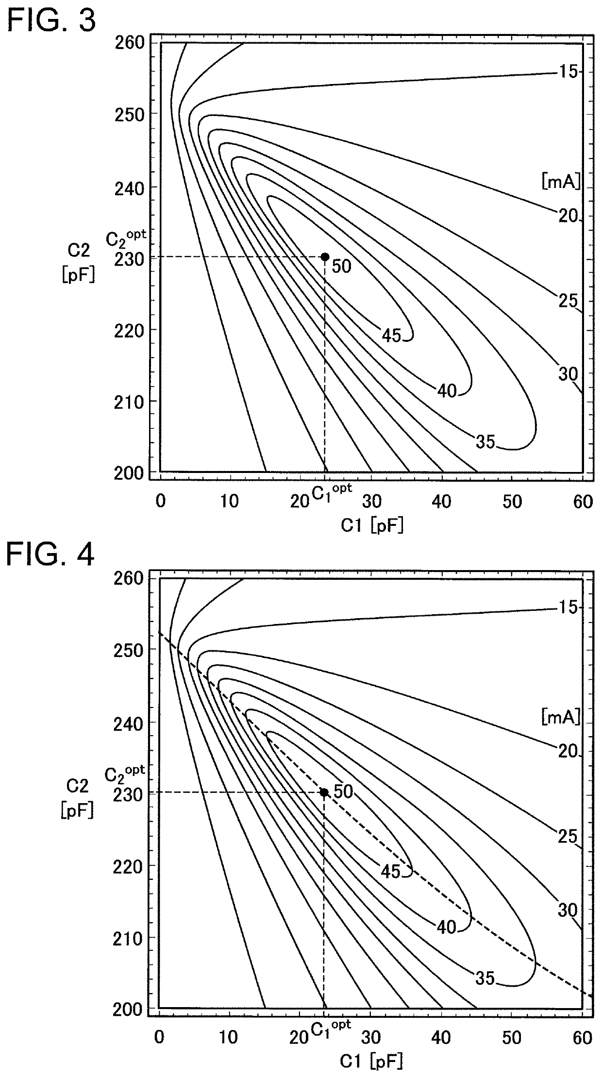
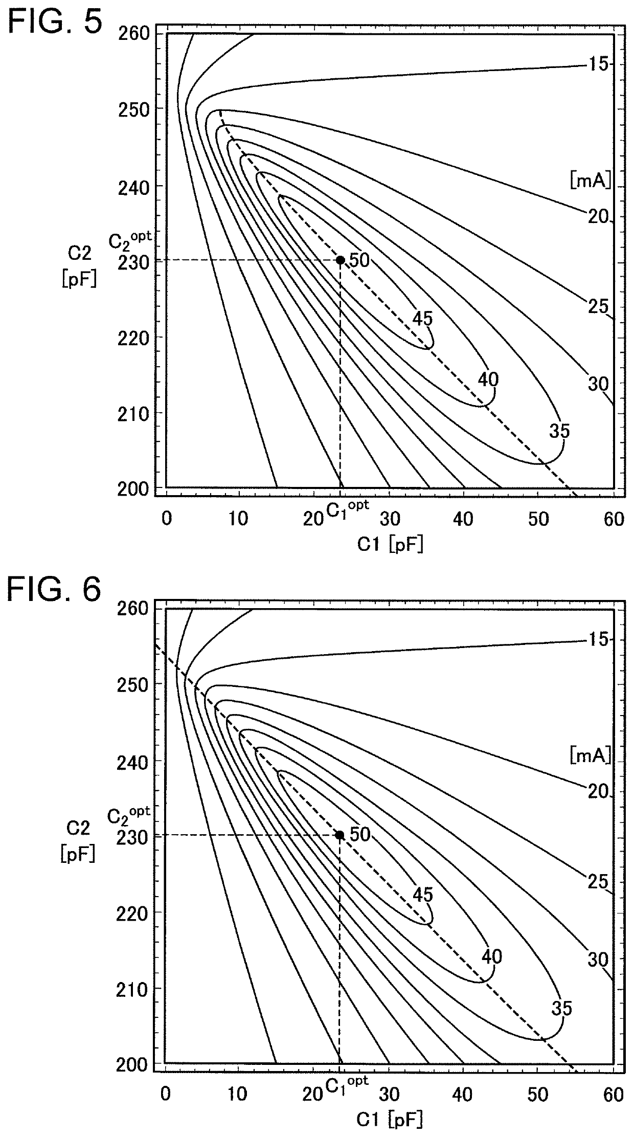
Even when at least one of a capacitor (C1) connected to a main loop and a capacitor (C2) connected to an amplification loop cannot be set to an optimal value, a current value of a current (I2) flowing on the amplification loop can be made sufficiently large by setting the capacitors (C1, C2) based on any of an optimal C2 curved line, an optimal C1 curved line, and an optimal C1 straight line that pass through an optimal point (C1opt, C2opt) of the capacitors (C1, C2) and extend along a ridge of contour lines each joining the points where the magnitude of the current (I2) is equal on a diagram showing a relation of values of the capacitors (C1, C2) with the magnitude of the current (I2).

Description

TECHNICAL FIELD[0001]The present invention relates to a loop antenna that can contribute to expansion of a coverage for a wireless system using a magnetic field.BACKGROUND ART[0002]In recent years, a service linked to an intention and an action of a user while purposely restricting an authentication area has been provided by using an authentication system adopting wireless communication techniques such as the near field communication (NFC) (Patent Documents 1 to 3). A loop antenna (a coil) is employed when forming the authentication area by using a magnetic field. A current applied to the antenna develops spherical magnetic field distribution on a surface of the antenna. A distance decay property of the magnetic field is shaper than that of an electric wave, and therefore has an advantage that it is possible to clearly mark off a boundary of a wireless coverage.[0003]The sharp distance decay property of the magnetic field is a drawback from the viewpoint of expanding the wireless co...

Claims


Application Information

Patent Timeline
Patent Type & Authority Patents(United States)
IPC IPC(8): H01Q7/08H04B5/02H01Q19/02
CPCH01Q19/02H01Q7/08H04B5/02H04B5/0081
Inventor SASAKI, AI-ICHIROKODATE, JUNICHI
Owner NIPPON TELEGRAPH & TELEPHONE CORP
Learn More