
Textile fabric magnetization dyeing and finishing device

A technology of textile fabrics and magnetizers, which is applied in the processing of textile materials, liquid/gas/steam textile materials, textiles and papermaking, etc. It can solve the problem of destroying association water molecule groups, unsatisfactory magnetization effects, and poor magnetization effects. Good and other problems, to achieve greater water solubility, save dyes, and improve the effect of magnetization

Inactive Publication Date: 2014-06-25
ZHANGJIAGANG HUAYUAN DYEING & WEAVING
View PDF3 Cites 0 Cited by
  • Summary
  • Abstract
  • Description
  • Claims
  • Application Information

AI Technical Summary

Problems solved by technology

[0003] However, there are currently two main devices for magnetizing water in the process of printing and dyeing fabrics. One is to directly install a simple magnetizer on the water supply pipe to pre-magnetize the water added to the printing and dyeing tank. The magnetization effect of this device is Not good, the magnetization time in the magnetizer is short due to the flow rate in the water supply pipe, therefore, there is not enough time to destroy the associated water molecule groups
The other is to put a simple magnetizer in the printing and dyeing tank, and the fabric passes through the magnetizer. However, the magnetizer can only magnetize the local dye solution in the printing and dyeing tank, and the magnetization effect is not ideal.

Method used


Image

  • Textile fabric magnetization dyeing and finishing device

Examples


Embodiment Construction

[0013] The present invention will be further described in detail below through specific embodiments.

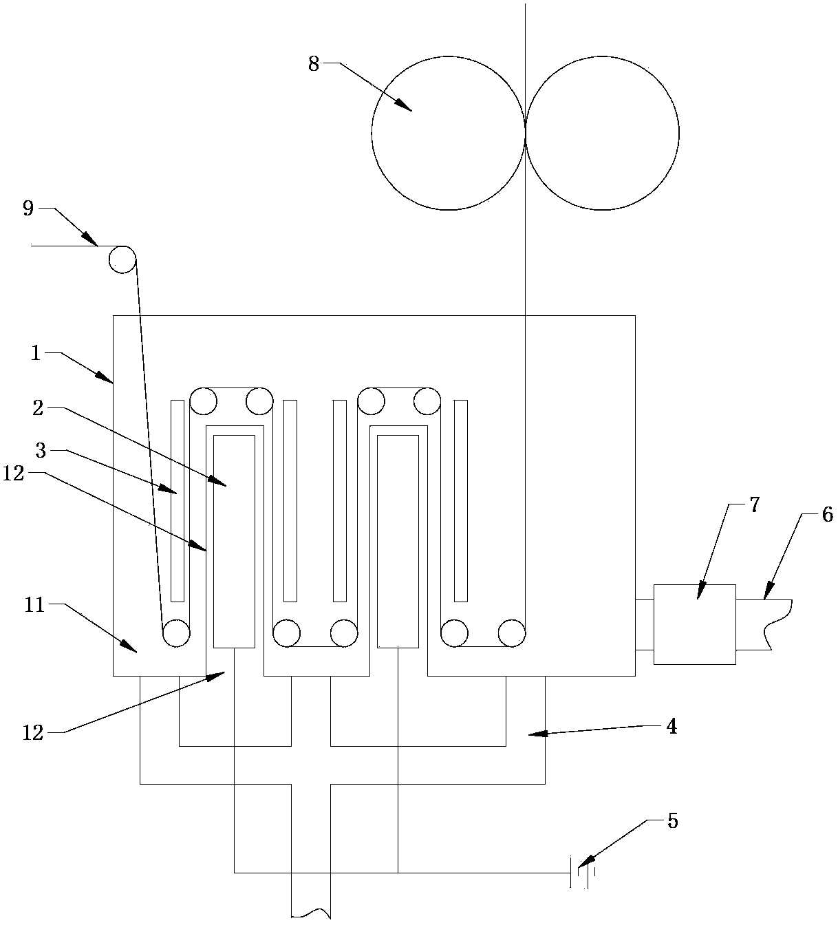
[0014] Such as figure 1 As shown, a textile fabric magnetized printing and dyeing device includes a printing and dyeing tank 1 provided with an inlet. The bottom of the printing and dyeing tank 1 is recessed to form a number of strip-shaped protrusions. From the inside of the printing and dyeing tank 1, these strips The printing and dyeing tank 1 is divided into several printing and dyeing cavities connected at the upper end by the shaped protrusions. When viewed from the bottom of the printing and dyeing tank 1, a number of concave cavities are formed on the bottom. The printing and dyeing tank 1 is provided with several guide rollers. And several guide rollers pass through the printing and dyeing chamber in turn, and then lead out, each printing and dyeing chamber is fixedly installed with a soft magnetic material plate 3, and an electromagnet 2 is provided in the concave cavi...


PUM


Abstract

The invention discloses a textile fabric magnetization dyeing and finishing device which is high and good in magnetization effect. The dyeing and finishing device comprises a dyeing and finishing tank which is provided with an inlet port. The bottom of the dyeing and finishing tank sinks upward to form a plurality of strip lug bosses which divide the dyeing and finishing tank into a plurality of dyeing and finishing cavities with the upper ends communicated with one another. Fabrics sequentially pass through the dyeing and finishing cavities through a driving roller and a plurality of guide rollers and then are led out. Plates made of soft magnetic material are fixedly installed inside all the dyeing and finishing cavities. Electromagnets are arranged inside the upward sunk cavities at the bottom of the dyeing and finishing tank, and the bottoms of all the dyeing and finishing cavities are communicated with an outlet pipeline.

Description

Technical field [0001] The invention relates to a printing and dyeing device, in particular to a magnetic printing and dyeing device for textile fabrics. Background technique [0002] The current textile fabric printing and dyeing process requires a lot of waste of water. The main reason is that most of the dye solution dyed on the fabric is dyed on the fabric, and a small part of the dye solution will be discharged as waste. Research has found that the nature The water does not exist as a single molecule. It is usually composed of larger groups of associated water molecules. This kind of water may destroy the group of associated water molecules under the action of a magnetic field, and form smaller groups of associated water molecules. Even a single water molecule. After magnetization, the water solubility becomes larger, the permeability is improved, and the activity is enhanced. It is used to configure the dye to dissolve faster, and the dye solution can penetrate the tissue ...

Claims


Application Information

Patent Timeline
Patent Type & Authority Patents(China)
IPC IPC(8): D06B23/00D06B3/10
Inventor 刘建华
Owner ZHANGJIAGANG HUAYUAN DYEING & WEAVING
Learn More