Methods and systems of holographic interferometry

a technology of interferometry and methods, applied in the field of holographic imaging, can solve the problems of general application slowness of the scheme, and achieve the effect of limiting spatial smearing and computationally cheaper

Active Publication Date: 2020-07-28
RD SYNERGY LTD
View PDF13 Cites 1 Cited by
  • Summary
  • Abstract
  • Description
  • Claims
  • Application Information

AI Technical Summary

Benefits of technology

[0009]More optionally, the holographic interferometer, simulating different wavelengths from a single wavelength light source, further comprises: a monochromatic coherent light source; and an optical setup which splits light from the light source into a first light beam which illuminates a subject structure and a second light beam which illuminates a reference mirror; and combines the first light beam and the second light beam to a single combined beam. Using different effective wavelength from a single wavelength light source thus removes the need for an expensive, multiple wavelength light source.
[0020]According to an aspect of some embodiments of the present invention there is provided a method of obtaining height measurement of a subject structure from an image produced by a holographic interferometer, comprising: receiving a digital image of an interference pattern from an imaging device of a holographic interferometer, the interference pattern is created by an imaging of a subject structure; selecting a two-dimensional section of the image; analyzing the interference pattern in the two-dimensional section to calculate phase of the interference pattern; and estimating height of a respective section of the subject structure from the phase. This limits the spatial smearing and is computationally cheaper than common methods.

Problems solved by technology

However, such schemes are generally too slow for applications in which the object needs to be laterally scanned in limited time, such as wafer inspection.

Method used


Image

  • Methods and systems of holographic interferometry
  • Methods and systems of holographic interferometry
  • Methods and systems of holographic interferometry

Examples


Embodiment Construction

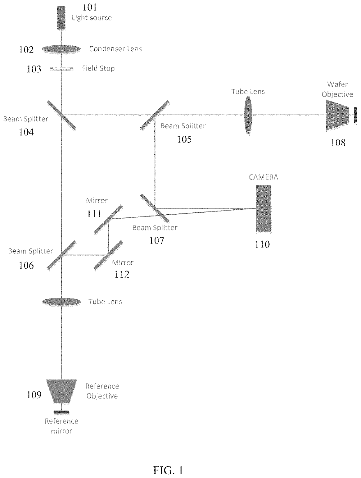
[0044]The present invention, in some embodiments thereof, relates to holographic imaging and, more particularly, but not exclusively, to methods and systems of three dimensional measurements using holographic interferometry.

[0045]According to some embodiments of the present invention, there is provided a holographic interferometer having identical optical paths for the object beam and the reference beam, to maximize uniformity of the interference lines on the field of view. This is done by constructing a reference image of a mirror, with essentially the same optical path that is used for constructing the object image.

[0046]In many optical setups, it may be difficult to achieve uniform interference line density across the entire field-of-view, as even when the optics is diffraction limited and the object is in focus, the phase of an image point (relative to, for example, the image point at the center of field with a flat object field) may change rapidly when moving across the field, ...


PUM

PropertyMeasurementUnit
angleaaaaaaaaaa
sizeaaaaaaaaaa
shapeaaaaaaaaaa

Abstract

A holographic interferometer, comprising: at least one imaging device capturing an interference pattern created by at least two light beams; and at least one aperture located in an optical path of at least one light beam of the at least two light beams; wherein the at least one aperture is located away from an axis of the at least one light beam, thus transmitting a subset of the at least one light beam collected at an angle range.

Description

FIELD AND BACKGROUND OF THE INVENTION[0001]The present invention, in some embodiments thereof, relates to holographic imaging and, more particularly, but not exclusively, to methods and systems of three dimensional measurements using holographic interferometry.[0002]Holographic imaging, which records amplitude and phase information of light arriving from an object (such as integrated circuit (IC) semiconductor wafers or flat panel display (FPD)), may be used in microscopy to reconstruct the 3D profile of the object, i.e. the relative height of each point in the image.[0003]Some methods use zero angle between the object and reference image, and a phase scanning mechanism, which, combined with multiple image acquisitions at the same object location, give the possibility to separate between the phase and amplitude information. These methods may even use illumination with a very short coherent length. However, such schemes are generally too slow for applications in which the object need...

Claims


Application Information

Patent Timeline
Patent Type & Authority Patents(United States)
IPC IPC(8): G03H1/04G01B11/24G01B9/02G03H1/26
CPCG01B11/2441G01B9/02097G03H1/0443G01B9/02005G03H1/0402G01B9/02032G03H1/265G03H2226/13G03H2222/13G03H2001/0456G03H2001/266G01B2290/45G03H2001/046
Inventor FURMAN, DOV
Owner RD SYNERGY LTD
Why Eureka
Try Eureka