Supercharge Your Innovation With Domain-Expert AI Agents!

Aircraft joint

a technology for aircraft wings and joints, applied in the field of aircraft joints, can solve the problems of aircraft wing leading edge panels being subjected to particularly harsh environmental conditions, fastener heads and fastener holes conventionally used to attach leading edge panels to leading edge ribs and to the wing covers are unlikely to be able to meet this step condition, and the ability to retain laminar flow is significantly affected, so as to achieve the effect of convenient assembly and/or disassembly of the join

Active Publication Date: 2020-08-04
AIRBUS OPERATIONS LTD
View PDF7 Cites 1 Cited by
  • Summary
  • Abstract
  • Description
  • Claims
  • Application Information

AI Technical Summary

Benefits of technology

[0010]The invention is advantageous in that the strap assembly is fully concealed below the outer aerodynamic surfaces at the joint and has no parts exposed in the outer aerodynamic surfaces at the joint. This improves the ability to retain laminar flow (natural, passive, active or hybrid laminar flow) at the joint where this is desirable. The sliding connection of the third strap part in the first and second strap parts allows for ease of assembly and / or disassembly of the joint.
[0011]The third strap part constrains movement of the first component relative to the second component in a direction normal to the outer aerodynamic surfaces of the first and second components in the vicinity of the strap assembly. Constraining movement thereby provides a generally fixed or rigid joint, equivalent to a joint secured by fasteners. Thus, the strap assembly prevents, or minimises, relative movement between the first and second components that may cause a disruption to the outer aerodynamic profile, such as a drag-inducing step between respective edges of the first and second components. The joint may hold or maintain the first component in a generally fixed position relative to the second component, so that the outer aerodynamic surfaces of the first and second components may be substantially flush across the joint.
[0024]Alternatively the first and second components may be an access panel and a surrounding structure or fairing. The access panel may be easily removed for access to services or the like behind the panel. The surrounding structure may be an aircraft fuselage, empennage, nose, etc. or a fairing, e.g. a belly fairing, wing root joint fairing, etc. The benefits of ease of assembly / disassembly of the joint may be enjoyed both in location where maintenance of laminar flow over the outer aerodynamic surfaces at the joint is important and in locations where this is not important.

Problems solved by technology

Surface roughness of the outer aerodynamic surface, particularly at the upper surface leading edge, will significantly affect the ability to achieve laminar flow.
The fastener heads and fastener holes conventionally used to attach leading edge panels to leading edge ribs and to the wing covers are unlikely to be able to satisfy this step condition.
Furthermore, aircraft wing leading edge panels are subjected to particularly harsh environmental conditions.
Removal of very many fasteners joining the leading edge panel to the leading edge ribs and the wing cover, and installation of a new panel again with very many fasteners, is time consuming leading to costly downtime of the aircraft for maintenance.
This problem may be exacerbated by a move to natural laminar flow aerofoils, as the tighter tolerance for surface smoothness may lead to more frequent leading edge panel replacements.

Method used


Image

  • Aircraft joint
  • Aircraft joint
  • Aircraft joint

Examples


Embodiment Construction

)

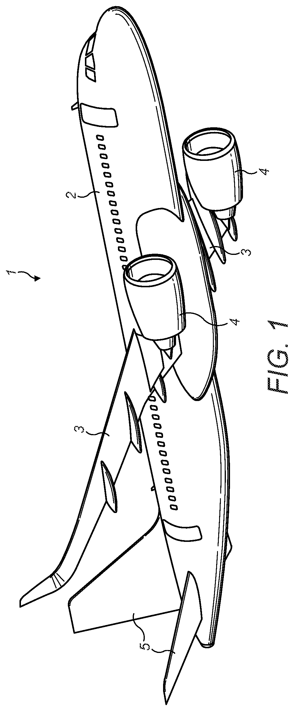
[0036]FIG. 1 illustrates a typical configuration for a fixed wing passenger transonic jet transport aircraft 1. The aircraft 1 comprises a fuselage 2, wings 3, main engines 4 and horizontal and vertical tailplanes 5. It will be appreciated that this invention is applicable to a wide variety of aircraft types not just that illustrated in FIG. 1. For example, the aircraft, may be for commercial or military purposes, may be for transporting passengers or cargo, may have jet, propeller or other engine propulsion systems, may have a variety of fuselage / wing configurations, e.g. a high wing, low wing or blended wing body, and may be designed to fly at subsonic, transonic or supersonic speeds.

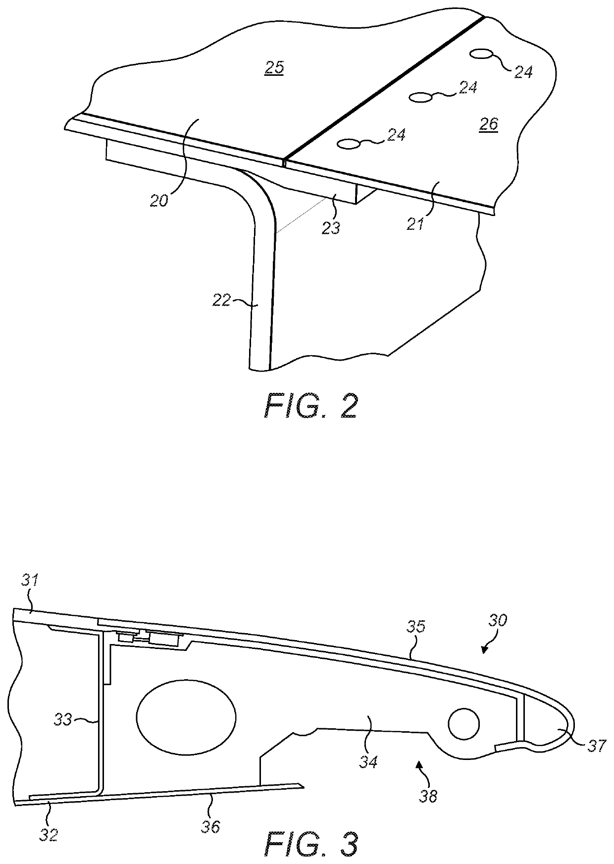
[0037]FIG. 2 illustrates a known joint between an upper wing cover 20 and a wing leading edge panel 21. The upper wing cover 20 is attached to a front spar 22. A forward edge of the upper wing cover 20 includes a joggle 23 and the wing leading edge panel 21 is fastened to the upper wing cover 20 by a...


PUM


Abstract

An aircraft joint includes a first component having an outer aerodynamic surface and an inner surface, a second component having an outer aerodynamic surface and an inner surface, and a strap assembly bridging between the inner surfaces of the first and second components. The strap assembly has a first strap part attached to the inner surface of the first component, a second strap part attached to the inner surface of the second component, and a third strap part received in the first and second strap parts in a sliding manner. The third strap part when received in the first and second strap parts constrains movement of the first component relative to the second component in a direction normal to the outer aerodynamic surfaces of the first and second components in the vicinity of the strap assembly.

Description

RELATED APPLICATION[0001]This application claims priority to United Kingdom Patent Application GB1608287.7 filed May 11, 2016, the entire contents of each of which are hereby incorporated by reference.FIELD OF THE INVENTION[0002]The present invention relates to a joint between two components. The invention also relates to a method of forming such a joint.BACKGROUND OF THE INVENTION[0003]Aircraft wings commonly comprise a wing box structure with spanwise extending front and rear spars, and ribs extending chordwise between the front and rear spars. Upper and lower wing covers extend between the spars to form the upper and lower boundaries of the wing box. Leading and trailing edge structures, forward and aft of the front and rear spars respectively, typically comprise ribs and panels. Trailing edge panels are commonly substantially planar, whereas leading edge panels are commonly curved.[0004]The covers and panels are typically fastened to the ribs and spars. The leading and trailing ...

Claims


Application Information

Patent Timeline
Patent Type & Authority Patents(United States)
IPC IPC(8): B64C3/28B64C3/26
CPCB64C3/28B64C3/26F16B11/006B64C1/12F16B5/0012
Inventor SALISBURY, ROSS
Owner AIRBUS OPERATIONS LTD
Features
  • R&D
  • Intellectual Property
  • Life Sciences
  • Materials
  • Tech Scout
  • Unparalleled Data Quality
  • Higher Quality Content
  • 60% Fewer Hallucinations
Learn More