Supercharge Your Innovation With Domain-Expert AI Agents!

Liquid crystal display panel with adjustable viewing angle and method for adjusting the viewing angle thereof

a technology of liquid crystal display panel and viewing angle, which is applied in the field of display, can solve the problems of increased production cost, inconvenient operation, and particularly urgent requirements, and achieves the effects of improving production efficiency, reducing production costs, and improving production efficiency

Active Publication Date: 2020-08-18
TCL CHINA STAR OPTOELECTRONICS TECH CO LTD +1
View PDF2 Cites 0 Cited by
  • Summary
  • Abstract
  • Description
  • Claims
  • Application Information

AI Technical Summary

Benefits of technology

This solution provides a stable and efficient method to adjust viewing angles, improving performance and reducing power consumption and size constraints, while maintaining a better technical effect compared to prior art.

Problems solved by technology

As to portable electronic devices using liquid crystal display, such as cell phones, palmtops, and laptops, such requirement is especially urgent.
Such approach requires the user to carry the shutter barrier film along, and thus is very inconvenient to operate.
However, in such method, the production cost, thickness and the energy consumption of the liquid crystal display panel will be increased undoubtedly.
In such method, multiple electrode drivers are generally needed, which are complicated to be realized.
The abovementioned liquid crystal display panel cannot satisfy requirements for portable electronic devices in both aspects of size and power consumption.
However, the electric field generated as such is rather weak, and thus a viewing angle control effect obtained therein is poor.

Method used


Image

  • Liquid crystal display panel with adjustable viewing angle and method for adjusting the viewing angle thereof
  • Liquid crystal display panel with adjustable viewing angle and method for adjusting the viewing angle thereof
  • Liquid crystal display panel with adjustable viewing angle and method for adjusting the viewing angle thereof

Examples


embodiment 1

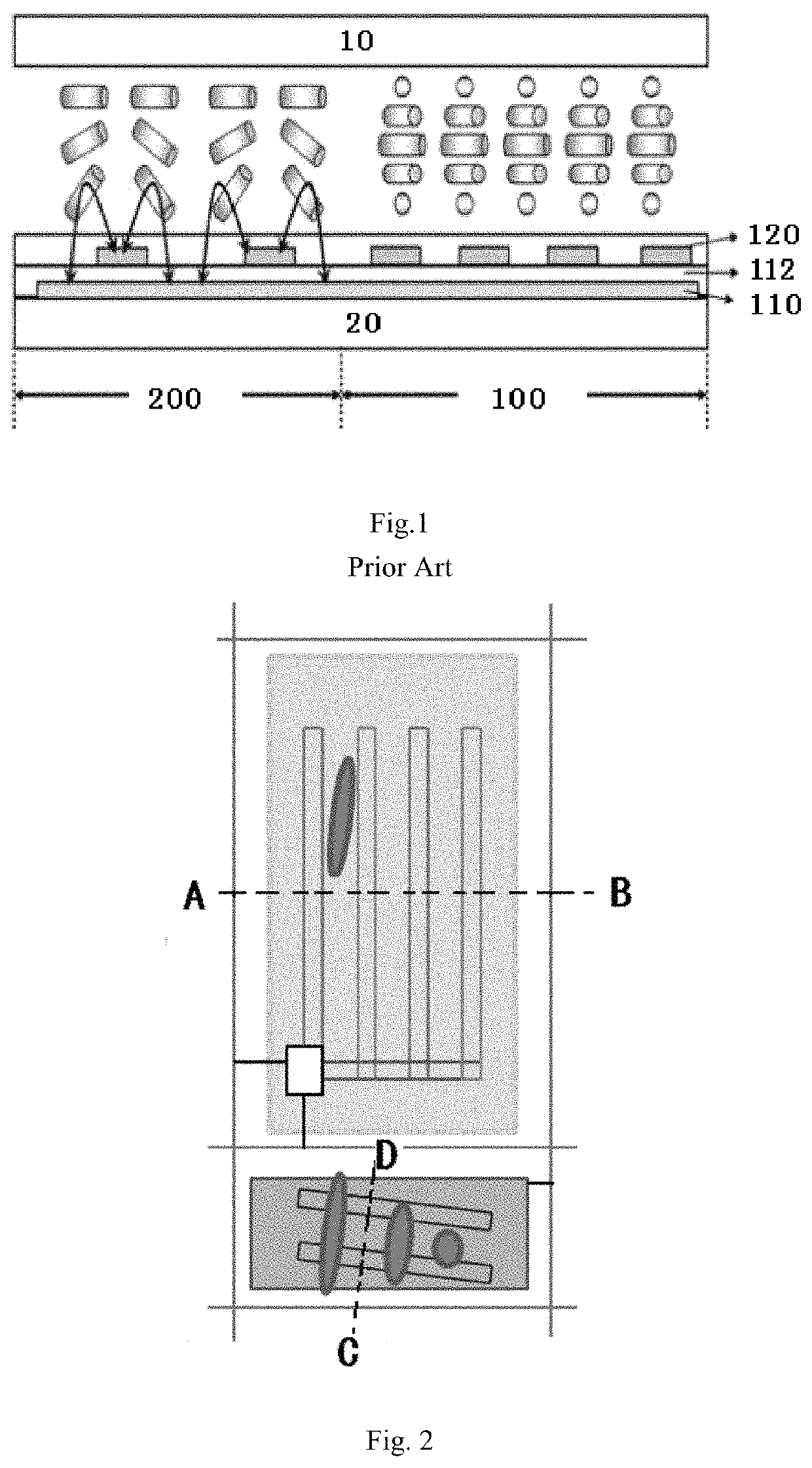
[0034]Similar to a liquid crystal display panel in the prior art, a liquid crystal display panel according to the present embodiment of the present disclosure comprises an upper substrate and a lower substrate which are parallel to each other, as well as a liquid crystal layer arranged between the upper substrate and the lower substrate. It should be noted that, the technical solution according to the present disclosure is applicable to both positive liquid crystal and blue phase liquid crystal. Therefore, liquid crystal material of the liquid crystal layer is not be defined herein. FIG. 2 shows a top view of a pixel unit in a display area of the liquid crystal display panel according to the present embodiment of the present disclosure. As shown in FIG. 2, the pixel unit in the display area is mainly divided into a main pixel area 100 and a sub pixel area 200. The main pixel area 100 is horizontally aligned and has an electrode structure based on FFS display mode. In the main pixel ...

embodiment 2

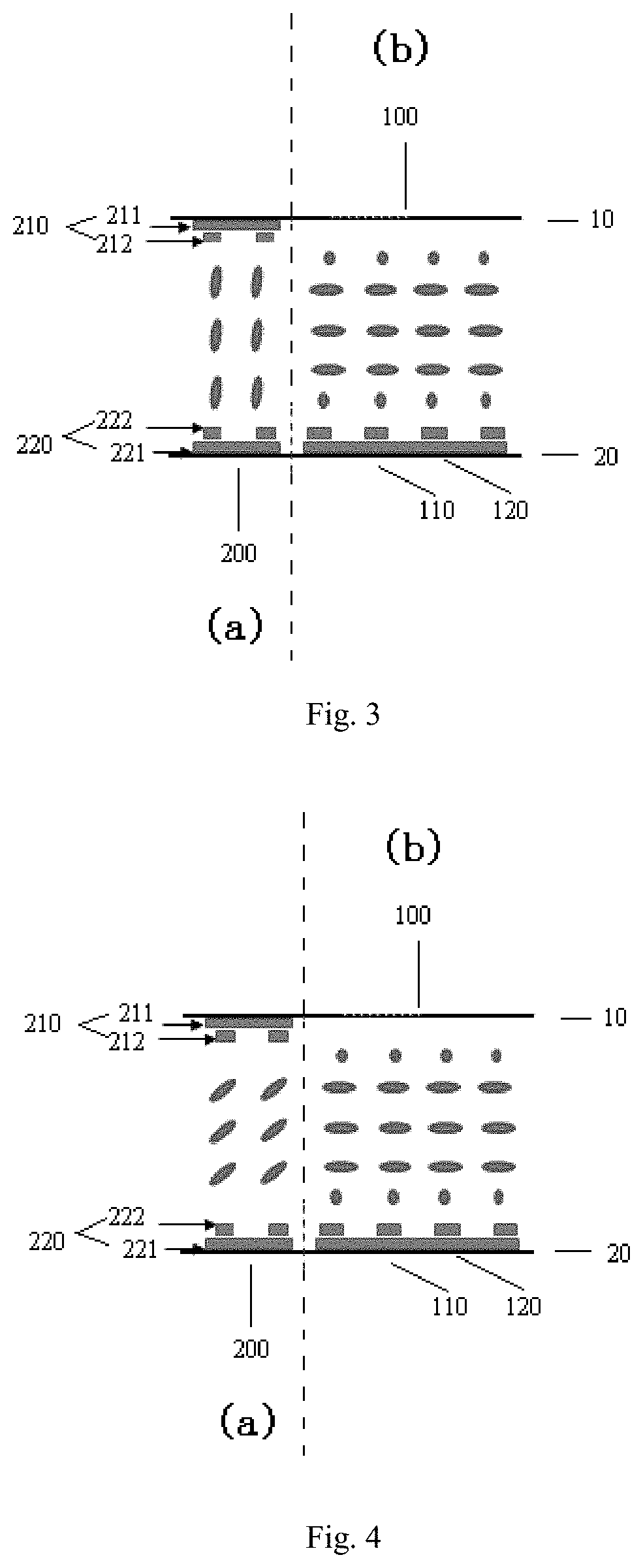
[0045]As shown in FIG. 3, in embodiment 2, an initial state of the liquid crystal molecules in the sub pixel area as shown in region (a) of FIG. 3 presents a vertical alignment. It should be noted that, the vertical alignment herein refers to a high, near 90° pre-tilt angle of the liquid crystal molecules. According to the present embodiment, a pre-tilt angle is 87°.

[0046]Under the narrow viewing angle mode, voltage is exerted only on the electrodes (pixel electrode and / or common electrode) in the main pixel area. Since the main pixel area is horizontally aligned, the liquid crystal molecules in the main pixel area rotate in the plane parallel to the upper substrate and the lower substrate. By controlling the voltage, an angle of rotation of the liquid crystal molecules in the plane parallel to the upper and lower substrates can be changed. In the meantime, since no bias voltage is exerted on the upper substrate electrode and the lower substrate electrode in the sub pixel area, the ...

embodiment 3

[0050]According to embodiment 3, an initial state of the liquid crystal molecules in the sub pixel area presents an oblique alignment. It should be noted that, the oblique alignment herein means that the liquid crystal molecules have a high pre-tilt angle, but are not entirely horizontal. In this case, a principle of switching between the narrowing viewing angle and the wide viewing angle is the same as embodiment 2. The only difference therefrom is a method of exerting bias voltages on the upper substrate electrode and the lower substrate electrode of the sub pixel area.

[0051]Under such circumstance, since the initial state of the liquid crystal molecules is oblique alignment, the bias voltages exerted on the upper substrate electrode and the lower substrate electrode of the sub pixel area should enable an electric field to have a strong enough vertical component between the upper substrate electrode and the lower substrate electrode, so that the liquid crystal molecules can stand ...


PUM

PropertyMeasurementUnit
angleaaaaaaaaaa
pre-tilt angleaaaaaaaaaa

Abstract

Disclosed are a liquid crystal display panel with adjustable viewing angle and a method for adjusting the viewing angle. A pixel unit located in a display area of the liquid crystal display panel includes a main pixel area and a sub pixel area. The main pixel area is horizontally aligned. The sub pixel area is vertically aligned. In the sub pixel area, an upper substrate electrode is arranged beneath the upper substrate and a lower substrate electrode is arranged on the lower substrate. In the sub pixel area, the upper substrate electrode and the lower substrate electrode both have a double layer electrode structure, and bias voltages, under an action of which liquid crystal molecules in the sub pixel area are aligned horizontally, vertically and obliquely, are exerted on the upper substrate electrode and the lower substrate electrode, thereby realizing switching between a narrow viewing angle mode and a wide viewing angle mode.

Description

CROSS-REFERENCE TO RELATED APPLICATIONS[0001]The present application claims benefit of Chinese patent application CN201510713568.2, entitled “Liquid Crystal Display Panel with Adjustable Viewing Angle and Method for Adjusting the Viewing Angle Thereof”, and filed on Oct. 28, 2015, the entirety of which is incorporated herein by reference.FIELD OF THE INVENTION[0002]The present disclosure relates to the technical field of display, and particularly to a liquid crystal display panel with adjustable viewing angle and a method for adjusting the viewing angle thereof.BACKGROUND OF THE INVENTION[0003]A viewing angle range (hereinafter referred to as viewing angle) is an important performance index of a liquid crystal display panel. In the liquid crystal display panel, a polarization state of light can be changed through regulating an alignment of liquid crystal molecules. In this manner, a flux between an upper polarizer layer and a lower polarizer layer can be controlled, and the display ...

Claims


Application Information

Patent Timeline
Patent Type & Authority Patents(United States)
IPC IPC(8): G02F1/133G02F1/1343G02F1/1337G02F1/13G02F1/137
CPCG02F1/13306G02F1/133753G02F1/1323G02F1/137G02F1/134363G02F2201/123G02F2001/134381G02F2201/121G02F1/134309G02F1/134381
Inventor TANG, YUEJUN
Owner TCL CHINA STAR OPTOELECTRONICS TECH CO LTD
Features
  • R&D
  • Intellectual Property
  • Life Sciences
  • Materials
  • Tech Scout
  • Unparalleled Data Quality
  • Higher Quality Content
  • 60% Fewer Hallucinations
Learn More