Eureka AIR delivers breakthrough ideas for toughest innovation challenges, trusted by R&D personnel around the world.

Investment casting pattern

a technology of investment casting and pattern, applied in the field of investment casting pattern, can solve the problems of reducing scrapping of the component, and unwanted surface and structural defects of the component casting, so as to reduce the efficiency and/or life of the component, reduce the number of manual steps, and simple, fast and effective

Active Publication Date: 2020-09-01
ROLLS ROYCE PLC +1
View PDF4 Cites 0 Cited by
  • Summary
  • Abstract
  • Description
  • Claims
  • Application Information

AI Technical Summary

Benefits of technology

[0005]Misalignment of the body portions of the pattern can cause unwanted surface and structural defects in the component cast using the pattern. These defects can reduce the efficiency and / or life of the component, or can mean that the component is scrapped. The use of the fastener reduces the number of manual steps required to assemble the pattern, and provides a positive location feature for aligning the body portions relative to each other. Therefore, the fastener provides a simple, fast, strong and effective means for aligning and joining the parts of the pattern in a repeatable manner, independent of operator skill improving consistency and manufacturing efficiency over a large number of parts.
[0007]The fastener may be formed of a polymer. The use of an appropriate polymer provides a fastener with the structural strength to hold the body portions together, whilst also enabling the fastener to be removed from the void in the mould. The first body portion and the second body portion may be formed of wax. A wax body is quick and inexpensive to make, and the wax can adopt complex geometries, with a high quality surface finish.
[0014]Misalignment of the body portions of the pattern can cause unwanted surface and structural defects in the component cast using the pattern. These defects can reduce the efficiency and / or life of the component, or can mean that the component is scrapped. The use of the fastener reduces the number of manual steps required to assemble the pattern, and provides a positive location feature for aligning the body portions relative to each other. Therefore, the fastener provides a simple, fast, strong and effective means for aligning and joining the parts of the pattern in a repeatable manner, independent of operator skill improving consistency and manufacturing efficiency over a large number of parts.
[0016]Chemically dissolving or melting the first body portion and the second body portion may also chemically dissolve or melt the fastener. Alternatively, the method may include chemically dissolving or melting the fastener separately from chemically dissolving or melting the first body portion and the second body portion. Chemically dissolving or melting the fastener may also cure the coating.
[0022]Misalignment of the body portions of the pattern can cause unwanted surface and structural defects in the component cast using the pattern. These defects can reduce the efficiency and / or life of the component, or can mean that the component is scrapped. The use of the fastener reduces the number of manual steps required to assemble the pattern, and provides a positive location feature for aligning the body portions relative to each other. Therefore, the fastener provides a simple, fast, strong and effective means for aligning and joining the parts of the pattern in a repeatable manner, independent of operator skill improving consistency and manufacturing efficiency over a large number of parts.

Problems solved by technology

Misalignment of the body portions of the pattern can cause unwanted surface and structural defects in the component cast using the pattern.
These defects can reduce the efficiency and / or life of the component, or can mean that the component is scrapped.

Method used


Image

  • Investment casting pattern
  • Investment casting pattern
  • Investment casting pattern

Examples


Embodiment Construction

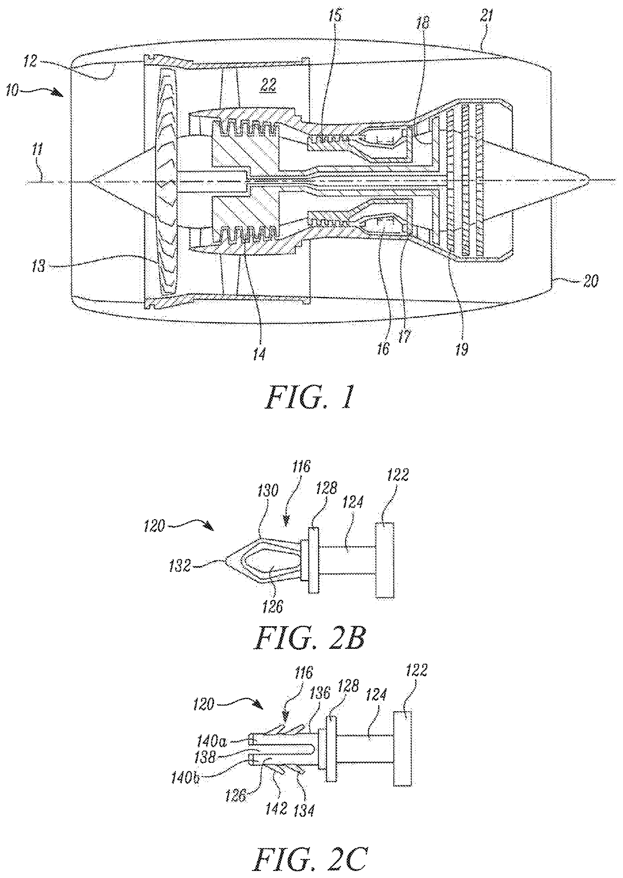
[0036]With reference to FIG. 1, a gas turbine engine is generally indicated at 10, having a principal and rotational axis 11. The engine 10 comprises, in axial flow series, an air intake 12, a propulsive fan 13, an intermediate pressure compressor 14, a high-pressure compressor 15, combustion equipment 16, a high-pressure turbine 17, an intermediate pressure turbine 18, a low-pressure turbine 19 and an exhaust nozzle 20. A nacelle 21 generally surrounds the engine 10 and defines both the intake 12 and the exhaust nozzle 20.

[0037]The gas turbine engine 10 works in the conventional manner so that air entering the intake 12 is accelerated by the fan 13 to produce two air flows: a first air flow into the intermediate pressure compressor 14 and a second air flow which passes through a bypass duct 22 to provide propulsive thrust. The intermediate pressure compressor 14 compresses the air flow directed into it before delivering that air to the high pressure compressor 15 where further comp...


PUM


Abstract

An investment casting pattern including: a consumable body formed of: a first body portion; and a second body portion; and a fastener arranged to form an interface between the first body portion and the second body portion, and to locate the first body portion relative to the second body portion, wherein the fastener is formed of a different material than the first body portion and the second body portion.

Description

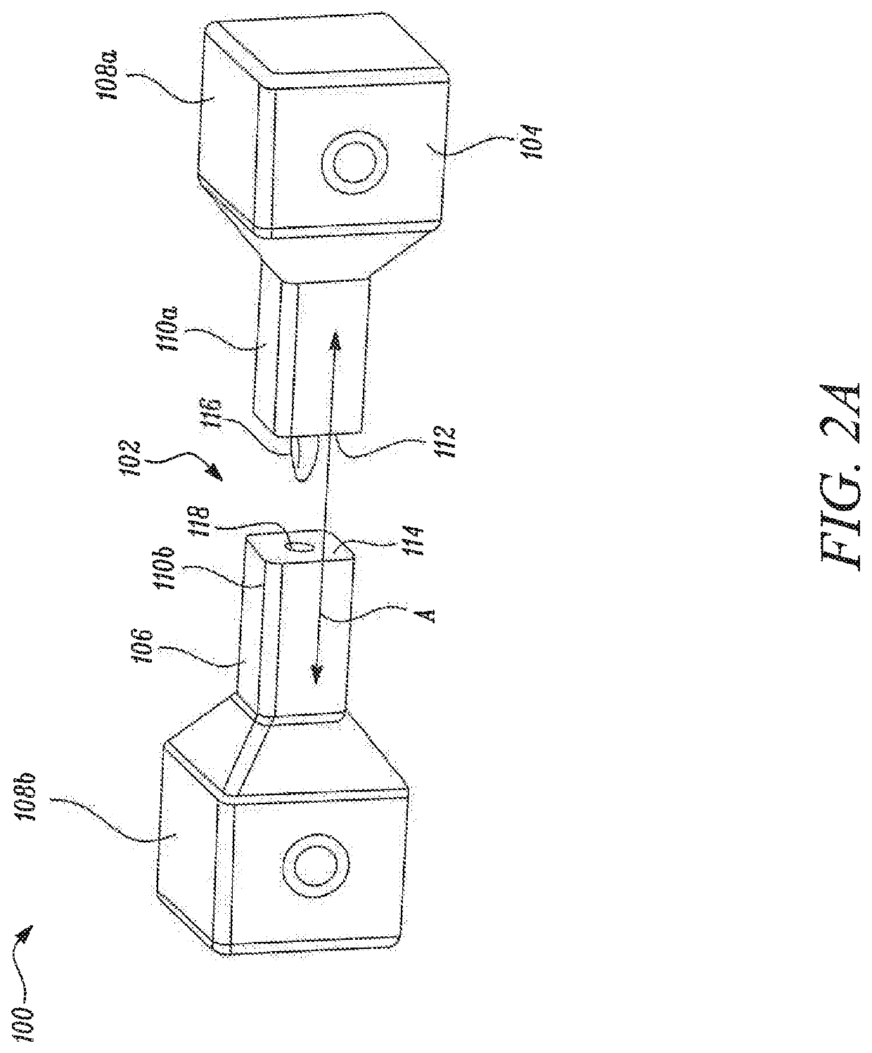
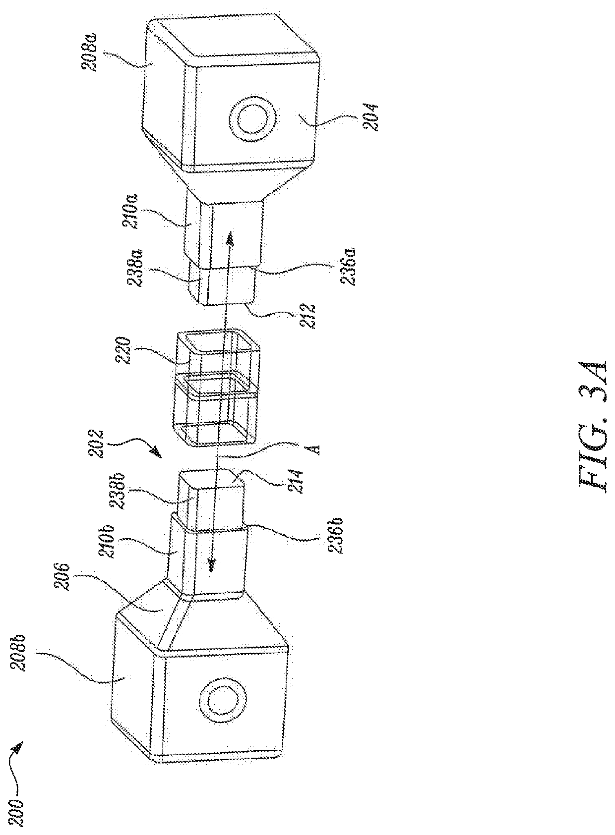
FIELD OF THE DISCLOSURE[0001]The present disclosure concerns an investment casting pattern, a method of investment casting a component and a fastener for locating and forming an interface between parts of a multi-part pattern.BACKGROUND OF THE DISCLOSURE[0002]In investment casting, a disposable or consumable pattern is formed in the shape of the component to be cast. The pattern is then coated in a ceramic, which sets to form a mould. The pattern is then removed from the mould, by melting or chemical leaching (dissolving) to leave a void in the mould, in the shape of the component to be cast. Molten metal is poured into the void, through the same opening that the pattern is removed through. The molten metal adopts the shape of the void, and hence the shape of the component to be formed. Once the metal is solidified, the mould is broken to remove the component.[0003]When making complex components by investment casting, the pattern may be formed in several parts, which have to be join...

Claims


Application Information

Patent Timeline
Patent Type & Authority Patents(United States)
IPC IPC(8): B22C7/02B22C9/04B33Y10/00B33Y80/00
CPCB22C7/02B22C9/04B33Y10/00B33Y80/00
Inventor ISLES, DAVID STEFANWIEBALCK, MAREIKEJESSON, PETERMULLAN, MARKHALL, CHRISTOPHER A
Owner ROLLS ROYCE PLC
Why Eureka
Eureka Blog
Learn More