
Surgical implant devices incorporating porous surfaces

a surgical implant and porous surface technology, applied in the direction of prosthesis, osteosynthesis device, manufacturing tool, etc., can solve the problems of insufficient bony purchase, mechanically manufactured friction surface, and insufficient effect of friction surfa

Active Publication Date: 2020-09-08
KYOCERA MEDICAL TECH INC
View PDF13 Cites 7 Cited by
  • Summary
  • Abstract
  • Description
  • Claims
  • Application Information

AI Technical Summary

Benefits of technology

The present invention provides a surgical implant device with a body portion and one or more surfaces that have protruding structures, such as needles, that are integrally formed with the body portion. The needles can be disposed perpendicular or at an angle to the body portion and can be made of titanium. The body portion has a hollow interior cavity and can have ports for bone screws or bony ingrowth. The method for manufacturing the implant device involves providing a body portion and forming the surfaces with protruding structures using an additive manufacturing process. The technical effect of this invention is an implant device with improved stability, addressing the problem of subsidence and providing greater bone ingrowth.

Problems solved by technology

However, these mechanically-manufactured friction surfaces, typically consisting of teeth, grooves, striations, or the like, are often not adequate and do little to promote bony purchase.
Similarly, these friction coatings or bondings may delaminate and fail.

Method used


Image

  • Surgical implant devices incorporating porous surfaces
  • Surgical implant devices incorporating porous surfaces
  • Surgical implant devices incorporating porous surfaces

Examples


Embodiment Construction

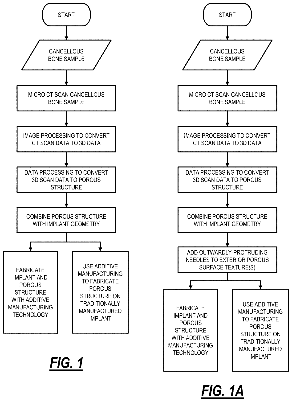
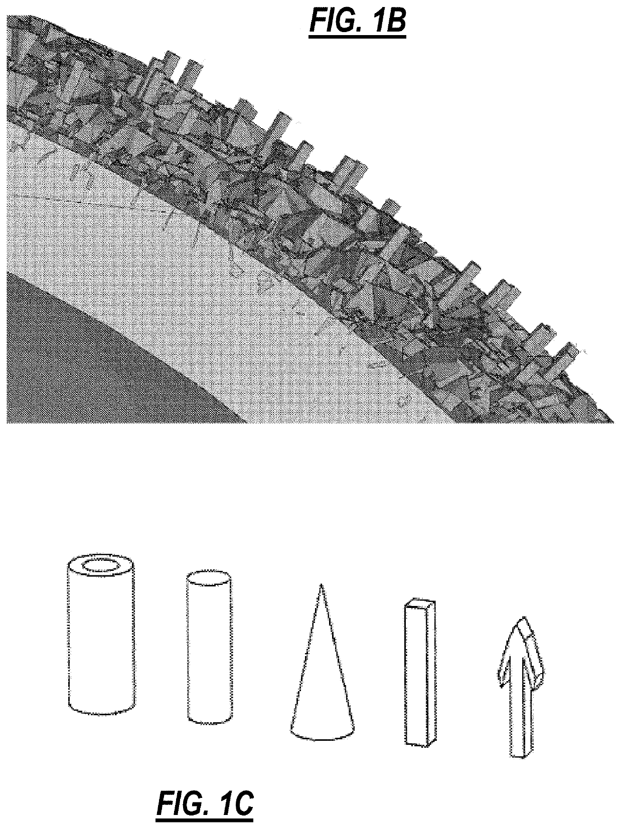
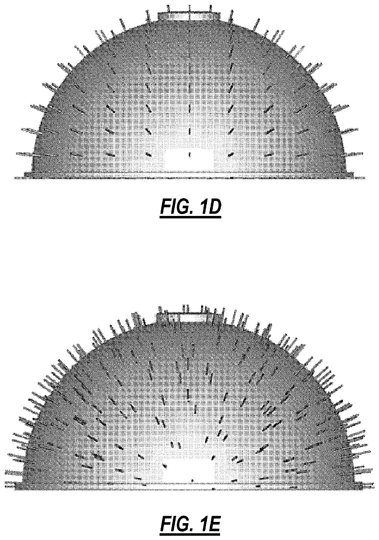
[0056]Generally speaking, and without intending to be limiting, one aspect of the invention relates to improved medical implants that include, for example, at least the following: a primary structure formed from metal; and at least one needle-populated, metallic surface portion formed on at least one exterior portion of the primary structure, the at least one surface portion located such that it engages with a patient's bone when the implant is implanted in the patient. Such needle-populated, metallic surface portions may contain, for example, a collection of at least fifty, a hundred, two hundred, five-hundred or more needles, and may be further characterized by at least one, two, three, four, five or more of the following characteristics: (a) the needles in the collection are all oriented substantially normal to the surface portion; (b) the needles in the collection are all oriented in substantially the same direction, with the direction being other than normal to the surface port...


PUM

PropertyMeasurementUnit
diametersaaaaaaaaaa
coefficient of frictionaaaaaaaaaa
shapesaaaaaaaaaa

Abstract

A surgical implant device, comprising: a body portion; and one or more surfaces comprising a plurality of protruding structures; wherein the body portion and the one or more surfaces comprising the plurality of protruding structures are integrally formed. The one or more surfaces comprising the plurality of protruding structures are formed by an additive manufacturing process. The plurality of protruding structures comprise a plurality of needles. Optionally, the surgical implant device comprises one of an anterior lumbar interbody fusion cage, a posterior lumbar interbody fusion cage, a transforaminal lumbar interbody fusion cage, an oblique lumbar interbody fusion cage, a cervical cage, and a bone screw.

Description

CROSS-REFERENCE TO RELATED APPLICATIONS[0001]The present patent application / patent claims the benefit of priority of: (1) U.S. Provisional Patent Application No. 61 / 857,824, filed on Jul. 24, 2013, and entitled “POROUS ANTERIOR LUMBAR INTERBODY FUSION CAGE,” (2) U.S. Provisional Patent Application No. 61,885,778, filed on Oct. 2, 2013, and entitled “POROUS ANTERIOR LUMBAR INTERBODY FUSION CAGE INCLUDING A LOCKING COVER PLATE,” and (3) U.S. Provisional Patent Application No. 61 / 916,469, filed on Dec. 16, 2013, and entitled “IMPLANTABLE MEDICAL DEVICES, INCLUDING POROUS SURFACES WITH FRICTION ENHANCING NEEDLE PROTRUSIONS, LATTICES FORMED FROM IRREGULAR UNIT CELLS, SLIGHTLY IRREGULAR LATTICES, ALL METAL INTERVERTEBRAL DEVICES, FUSION DEVICES HAVING MULTI CIRCULAR CROSS SECTIONAL PROFILES, AND METHODS FOR MAKING SAME USING ADDITIVE MANUFACTURING TECHNIQUES AND TREATING SAME WITH POST PROCESSING STEP TO ENHANCE SURFACE ROUGHNESS,” the contents of all of which are incorporated in full by ...

Claims


Application Information

Patent Timeline
Patent Type & Authority Patents(United States)
IPC IPC(8): A61F2/44A61F2/30A61F2/34B22F3/105B23K15/00B22F5/00A61B17/86
CPCA61F2/34A61F2/4465A61F2/447A61F2/30907B22F3/1055B23K15/00A61B17/86A61F2002/30777A61F2002/30784A61F2002/30011B22F2005/005A61F2002/30593A61F2002/30911A61F2002/30787Y02P10/25A61F2310/00023A61F2002/3093A61F2002/30785A61F2002/30517A61F2002/30507A61F2002/30774A61F2310/00796A61F2002/30909B22F10/28B22F10/80
Inventor STEINMANN, JOHN C.RUCKER, SCOTTRASMUSSEN, TIMSTEINMANN, JOHN P.CAWLEY, TRACEROSS, THOMASRIOS, ERNESTOOLCESE, ANDREW
Owner KYOCERA MEDICAL TECH INC
Learn More