
Uplink signal transmission method and user equipment

a technology of uplink signal and user equipment, applied in the field of wireless communication system, to achieve the effect of low cost/complexity, efficient transmission/receiving, and improved overall throughput of radio communication system

Active Publication Date: 2020-09-15
LG ELECTRONICS INC
View PDF3 Cites 2 Cited by
  • Summary
  • Abstract
  • Description
  • Claims
  • Application Information

AI Technical Summary

Benefits of technology

This approach enhances radio communication efficiency, reduces latency, and supports effective communication in new radio access technologies, enabling low-cost and low-complexity communication while maintaining compatibility with legacy systems.

Problems solved by technology

Also, massive machine type communication (MTC), which provides various services by connecting many devices and objects, is one of the major issues to be considered in the next generation communication.

Method used


Image

  • Uplink signal transmission method and user equipment
  • Uplink signal transmission method and user equipment
  • Uplink signal transmission method and user equipment

Examples


Embodiment Construction

[0037]Reference will now be made in detail to the exemplary embodiments of the present invention, examples of which are illustrated in the accompanying drawings. The detailed description, which will be given below with reference to the accompanying drawings, is intended to explain exemplary embodiments of the present invention, rather than to show the only embodiments that can be implemented according to the invention. The following detailed description includes specific details in order to provide a thorough understanding of the present invention. However, it will be apparent to those skilled in the art that the present invention may be practiced without such specific details.

[0038]In some instances, known structures and devices are omitted or are shown in block diagram form, focusing on important features of the structures and devices, so as not to obscure the concept of the present invention. The same reference numbers will be used throughout this specification to refer to the sa...


PUM


Abstract

According to the present invention, a user equipment (UE) receives semi-persistent scheduling (SPS) resource configuration information relating to SPS resources and receives an SPS command indicating activation or deactivation of the SPS resources. The UE flushes, in response to the SPS command, a buffer of an HARQ process associated with an SPS resource to transmit an SPS confirmation medium access control (MAC) control element (CE). The UE transmits a new MAC protocol data unit (PDU) including the SPS confirmation MAC CE on the SPS resource by using the HARQ process.

Description

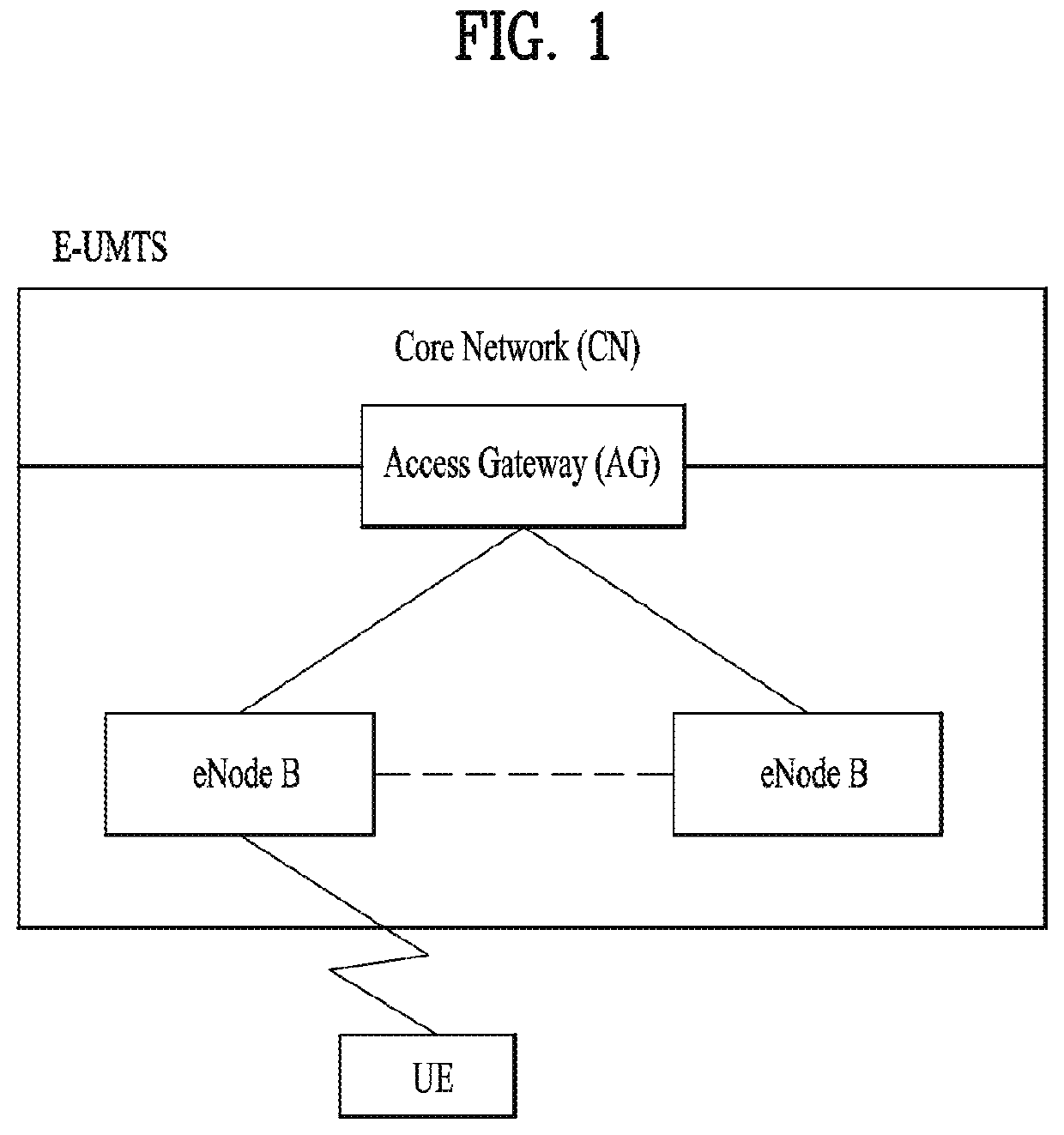
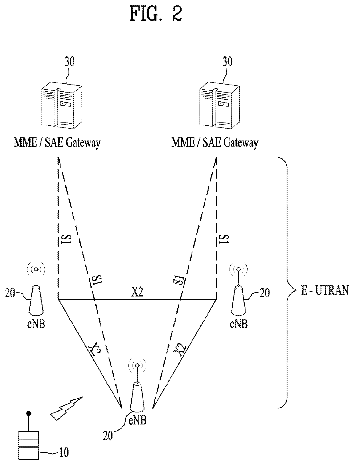
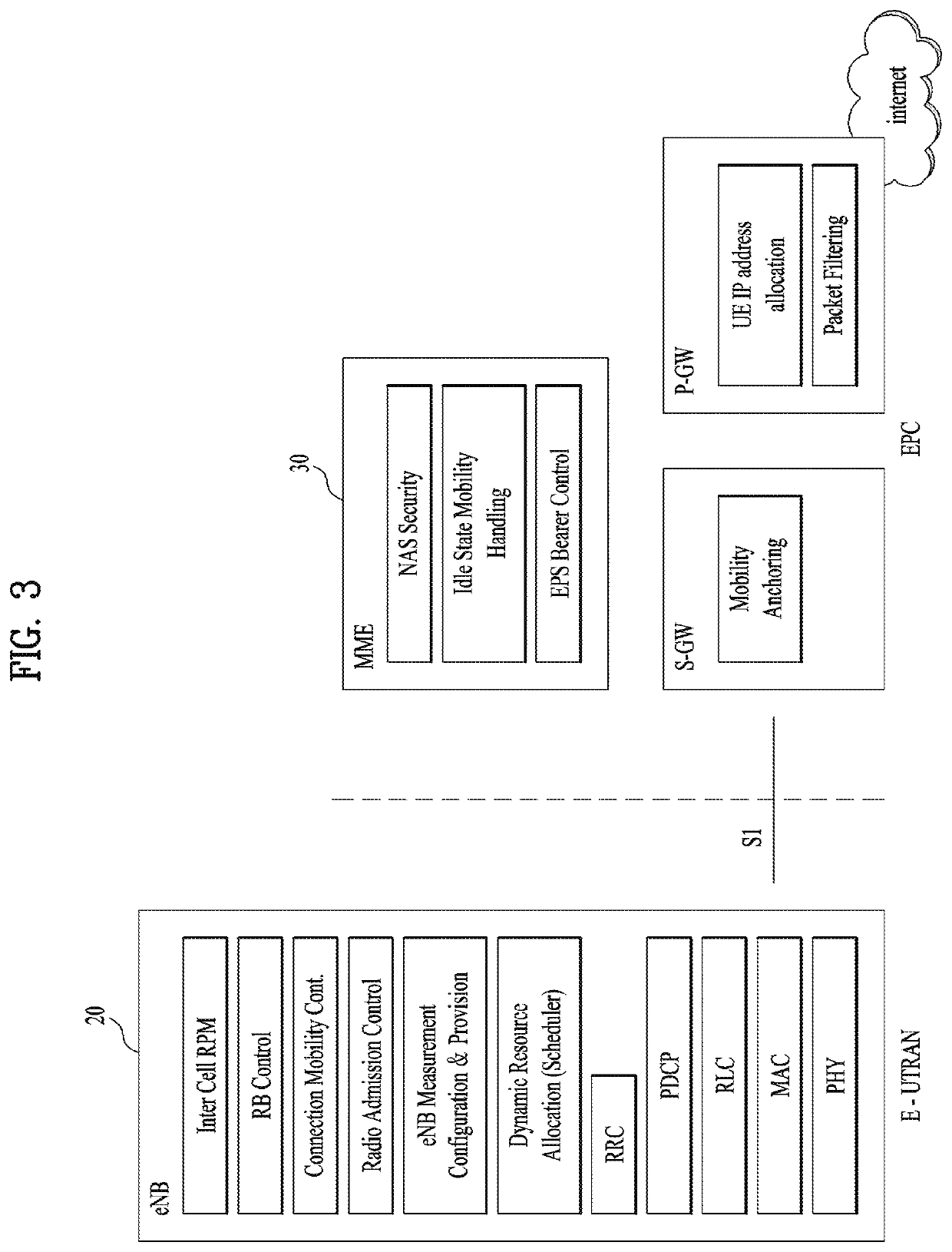
CROSS-REFERENCE TO RELATED APPLICATIONS[0001]This application is the National Stage filing under 35 U.S.C. 371 of International Application No. PCT / KR2017 / 007453, filed on Jul. 12, 2017, which claims the benefit of U.S. Provisional Application No. 62 / 361,492, filed on Jul. 12, 2016, the contents of which are all hereby incorporated by reference herein in their entirety.TECHNICAL FIELD[0002]The present invention relates to a wireless communication system, and more particularly, to a method for transmitting uplink signals and an apparatus therefor.BACKGROUND ART[0003]As an example of a mobile communication system to which the present invention is applicable, a 3rd Generation Partnership Project Long Term Evolution (hereinafter, referred to as LTE) communication system is described in brief.[0004]FIG. 1 is a view schematically illustrating a network structure of an E-UMTS as an exemplary radio communication system. An Evolved Universal Mobile Telecommunications System (E-UMTS) is an ad...

Claims


Application Information

Patent Timeline
Patent Type & Authority Patents(United States)
IPC IPC(8): H04L1/18H04W80/02H04W88/02H04W72/04
CPCH04W80/02H04L1/1812H04W72/0446H04W88/023H04L1/1819H04L1/1835H04L1/18H04W72/04
Inventor LEE, SUNYOUNGYI, SEUNGJUNE
Owner LG ELECTRONICS INC
Learn More