Unlock instant, AI-driven research and patent intelligence for your innovation.

Stepped heat shield for a turbine engine combustor

a technology of turbine engines and heat shields, which is applied in the direction of machines/engines, mechanical equipment, light and heating equipment, etc., can solve the problems of relatively high thermal stresses in the grommets and heat shields

Active Publication Date: 2020-10-06
RTX CORP
View PDF34 Cites 2 Cited by
  • Summary
  • Abstract
  • Description
  • Claims
  • Application Information

AI Technical Summary

Problems solved by technology

The quench aperture grommets as well as adjacent portions of the heat shield are typically subject to relatively high temperatures during turbine engine operation, which can induce relatively high thermal stresses within the grommets and the heat shield.

Method used


Image

  • Stepped heat shield for a turbine engine combustor
  • Stepped heat shield for a turbine engine combustor
  • Stepped heat shield for a turbine engine combustor

Examples


Embodiment Construction

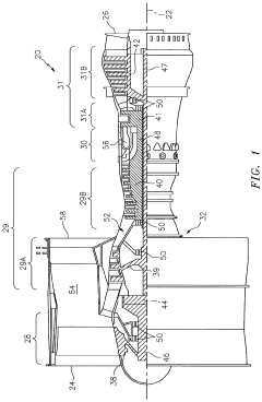
[0037]FIG. 1 is a side cutaway illustration of a geared turbine engine 20. This turbine engine 20 extends along an axial centerline 22 between a forward and upstream airflow inlet 24 and an aft and downstream core airflow exhaust 26. The turbine engine 20 includes a fan section 28, a compressor section 29, a combustor section 30 and a turbine section 31. The compressor section 29 includes a low pressure compressor (LPC) section 29A and a high pressure compressor (HPC) section 29B. The turbine section 31 includes a high pressure turbine (HPT) section 31A and a low pressure turbine (LPT) section 31B. The engine sections 28-31 are arranged sequentially along the centerline 22 within an engine housing 32.

[0038]Each of the engine sections 28, 29A, 29B, 31A and 31B includes a respective rotor 38-42. Each of the rotors 38-42 includes a plurality of rotor blades arranged circumferentially around and connected to one or more respective rotor disks. The rotor blades, for example, may be forme...


PUM


Abstract

An assembly is provided for a turbine engine. This turbine engine assembly includes a combustor wall with a shell and a heat shield. The combustor wall defines a quench aperture therethrough. The combustor wall also defines a cavity between the shell and the heat shield. The shell defines a first aperture through which air is directed into the cavity. The heat shield includes a rail that at least partially defines a second aperture configured to direct at least some of the air within the cavity out of the combustor wall and towards the quench aperture.

Description

[0001]This application claims priority to PCT Patent Application No. PCT / US15 / 014281 filed Feb. 3, 2015 which claims priority to U.S. Patent Application No. 61 / 935,135 filed Feb. 3, 2014, which are hereby incorporated herein by reference in their entireties.BACKGROUND OF THE INVENTION1. Technical Field[0002]This disclosure relates generally to a turbine engine and, more particularly, to a combustor for a turbine engine.2. Background Information[0003]A floating wall combustor for a turbine engine typically includes a bulkhead, an inner combustor wall and an outer combustor wall. The bulkhead extends radially between the inner and the outer combustor walls. Each combustor wall includes a shell and a heat shield, which defines a respective radial side of a combustion chamber. Cooling cavities extend radially between the heat shield and the shell. These cooling cavities may fluidly couple impingement apertures defined in the shell with effusion apertures defined in the heat shield.[0004...

Claims


Application Information

Patent Timeline
Patent Type & Authority Patents(United States)
IPC IPC(8): F23R3/00F02C7/24F23R3/06
CPCF02C7/24F23R3/002F23R3/06F23R2900/03044F05D2260/202F05D2260/201F23R2900/03042F23R2900/03041F05D2220/32F05D2240/35
Inventor MCKINNEY, RANDAL G.CUNHA, FRANK J.KOSTKA, JR., STANISLAV
Owner RTX CORP