Turbofan engine assembly and method of assembling same

a technology of turbine engines and parts, applied in the direction of machines/engines, marine propulsion, vessel construction, etc., can solve the problems of increasing the overall stage count, increasing the overall weight, increasing the design complexity, and/or the manufacturing cost of such an engin

Inactive Publication Date: 2008-05-29
GENERAL ELECTRIC CO
View PDF15 Cites 142 Cited by
  • Summary
  • Abstract
  • Description
  • Claims
  • Application Information

AI Technical Summary

Benefits of technology

[0004]In one aspect, a method of assembling a turbofan engine is provided. The method includes providing a core gas turbine engine including a high-pressure compressor, a combustor, and a turbine, coupling a first gearbox to a first fan assembly, and coupling a second gearbox to a booster compressor such that the booster compressor rotates in a rotational direction that is opposite to the rotational direction of the first fan assembly.

Problems solved by technology

However, while the use of a counter-rotating low-pressure turbine increases the overall engine efficiency, the counter-rotating low-pressure turbine also increases the overall stage count, thus increasing the overall weight, design complexity, and / or manufacturing costs of such an engine are increased.

Method used


Image

  • Turbofan engine assembly and method of assembling same
  • Turbofan engine assembly and method of assembling same
  • Turbofan engine assembly and method of assembling same

Examples


Embodiment Construction

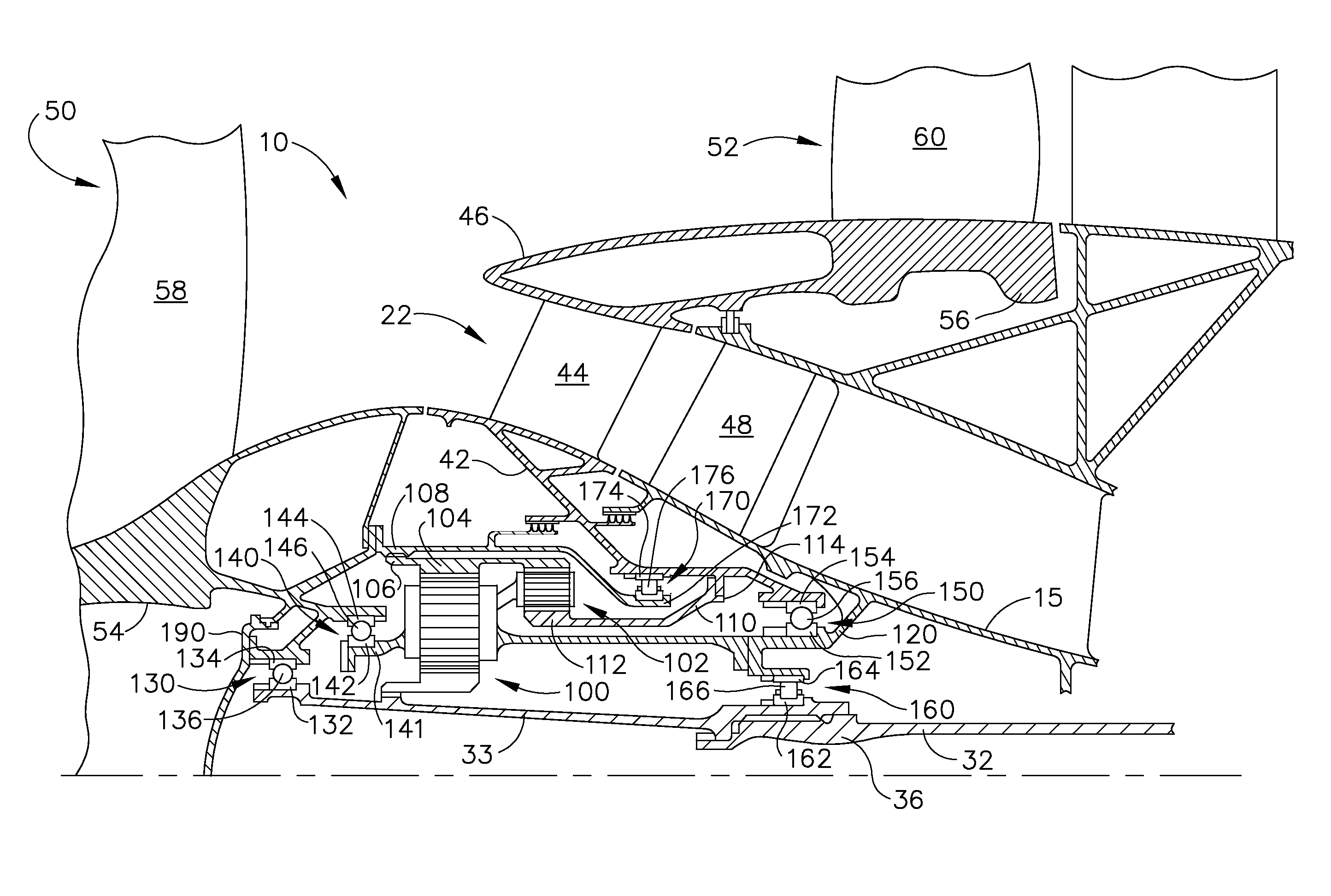
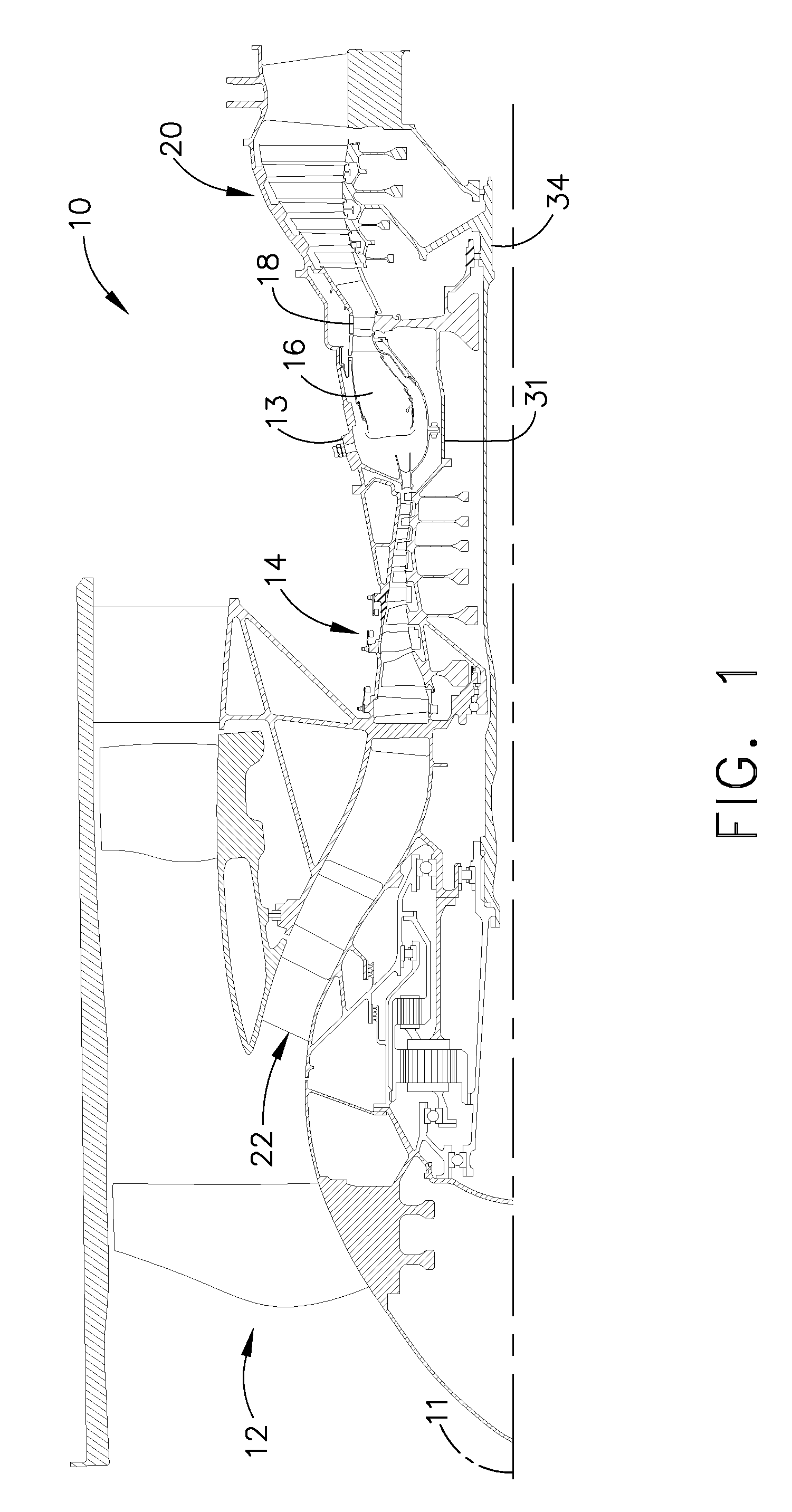
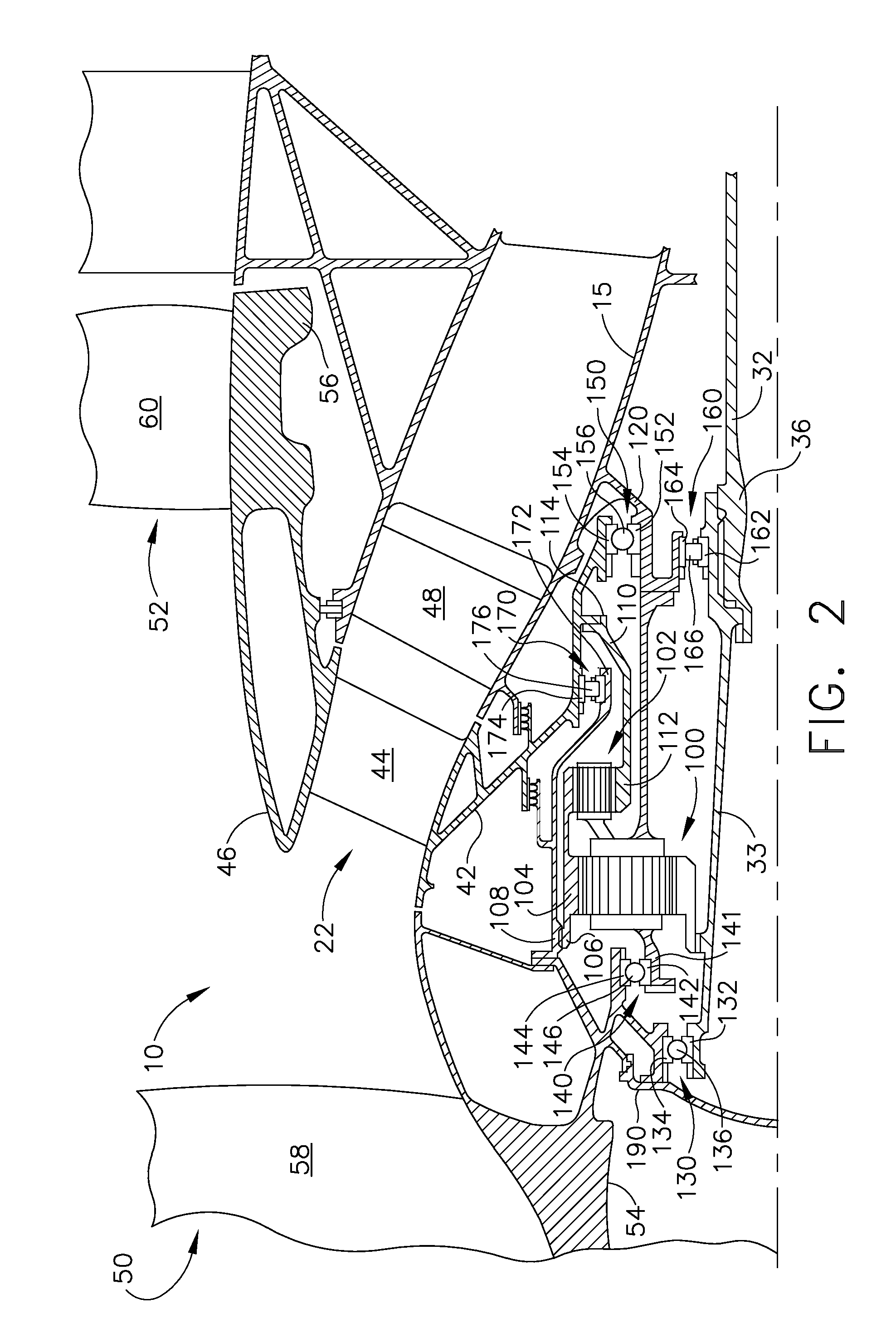
[0008]FIG. 1 is a schematic illustration of an exemplary turbofan engine assembly 10 having a longitudinal axis 11. Turbofan engine assembly 10 includes a fan assembly 12, a core gas turbine engine 13 that is disposed downstream from fan assembly 12, and a single-rotation low-pressure turbine 20 that is disposed downstream from the core gas turbine engine. The core gas turbine engine includes a high-pressure compressor 14, a combustor 16, a high-pressure turbine 18, and a first drive shaft 31 that is coupled between high-pressure compressor 14 and high-pressure turbine 18. In the exemplary embodiment, turbofan engine assembly 10 also includes a multi-stage counter-rotating booster compressor 22 that is disposed downstream from fan assembly 12 and upstream from core gas turbine engine 13. Turbofan engine assembly 10 also include a second drive shaft 32 that includes a first end 34 that is coupled or splined to low-pressure turbine 20 and a second end 36 that is coupled or splined to ...


PUM

PropertyMeasurementUnit
pressureaaaaaaaaaa
rotational speedaaaaaaaaaa
pressure balanceaaaaaaaaaa

Abstract

A turbofan engine assembly includes a core gas turbine engine including a high-pressure compressor, a combustor, and a high-pressure turbine, a first fan assembly disposed upstream from the core gas turbine engine, a first gearbox coupled to the first fan assembly, and a second gearbox coupled to a booster compressor such that the booster compressor rotates in a rotational direction that is opposite to the rotational direction of the first fan assembly. A method of assembling the above turbofan engine assembly is also described herein.

Description

BACKGROUND OF THE INVENTION[0001]This invention relates generally to gas turbine engines, and more specifically to a turbofan engine assembly that includes a counter-rotating booster compressor.[0002]At least some known turbofan engine assemblies include a fan assembly, a core gas turbine engine, and a low-pressure or power turbine. The core gas turbine engine includes at least one compressor, a combustor, and a high-pressure turbine that are coupled together in a serial flow relationship. Moreover, at least one known turbofan engine assembly includes a booster that is disposed between the fan assembly and the core gas turbine engine.[0003]To increase engine efficiency, at least one known turbofan engine assembly includes a counter-rotating low-pressure turbine that is coupled to a counter-rotating fan assembly. More specifically, to assemble a turbofan engine assembly that includes a counter-rotating low-pressure turbine, an outer rotating spool, a rotating frame, a mid-turbine fra...

Claims


Application Information

Patent Timeline
Patent Type & Authority Applications(United States)
IPC IPC(8): B23P15/00
CPCF02C3/107F02C7/36Y10T29/49236F05D2260/4031F02K3/072F05D2260/40311
Inventor SCHILLING, JAN CHRISTOPHER
Owner GENERAL ELECTRIC CO
Why Eureka
Try Eureka