Control system for a water heater

a control system and water heater technology, applied in the field of water heaters, can solve problems such as alarms to be initiated

Inactive Publication Date: 2002-06-18
AOS HLDG CO
View PDF25 Cites 145 Cited by
  • Summary
  • Abstract
  • Description
  • Claims
  • Application Information

AI Technical Summary

Benefits of technology

According to its main features and briefly stated, the present invention is a multiple function, solid state control system for a water heater. The control system comprises a control panel having a microprocessor, mounted to the exterior of the water heater, in electrical connection with a flammable gas sensor, positioned proximate to the air intake. Upon detecting a preselected concentration of a flammable gas, the sensor will issue a signal to the control panel which will prevent ignition of the burners, or shut them off if already in operation. A carbon monoxide sensor, positioned proximate to the draft hood, detects the presence of an unacceptable level of carbon monoxide, indicative of a blocked vent pipe, and also sends a signal to the microprocessor which will prevent, or discontinue, the operation of the burners. Both the flammable gas and carbon monoxide detector contain self-diagnostic circuitry which assures proper sensor operation. In addition, circuitry within the microprocessor monitors the service life of the sensors and will cause an alarm to be initiated when the sensors require replacement.

Problems solved by technology

In addition, circuitry within the microprocessor monitors the service life of the sensors and will cause an alarm to be initiated when the sensors require replacement.

Method used


Image

  • Control system for a water heater
  • Control system for a water heater
  • Control system for a water heater

Examples


Embodiment Construction

The present invention advances a multi-function controller for a water heater which centrally and simultaneously controls and monitors a variety of operational parameters.

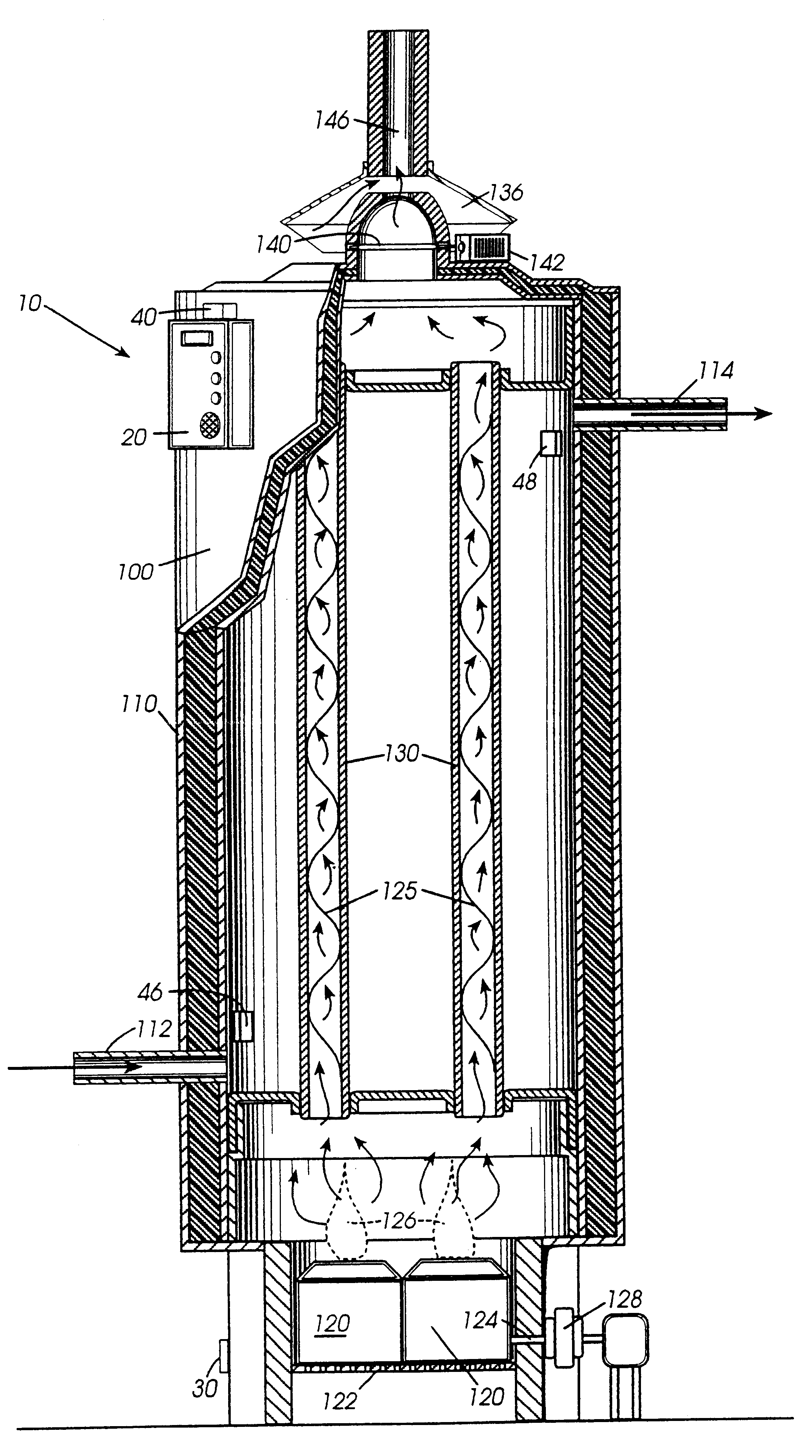
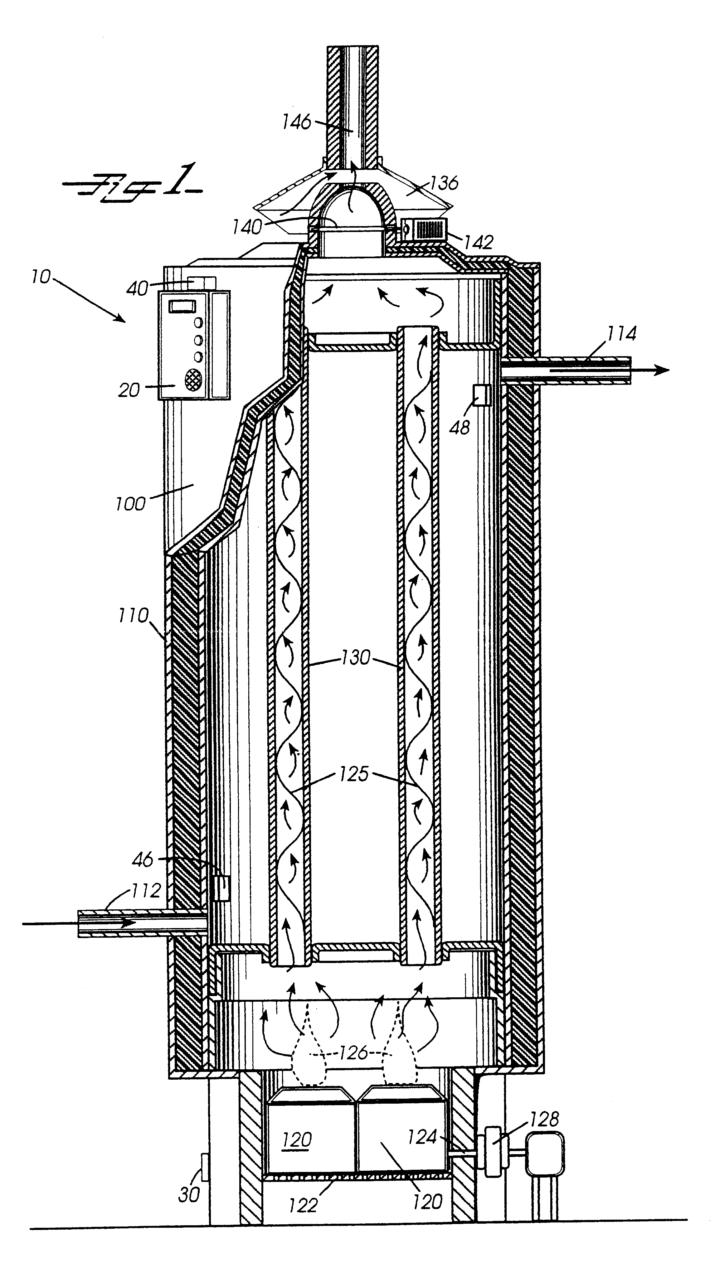
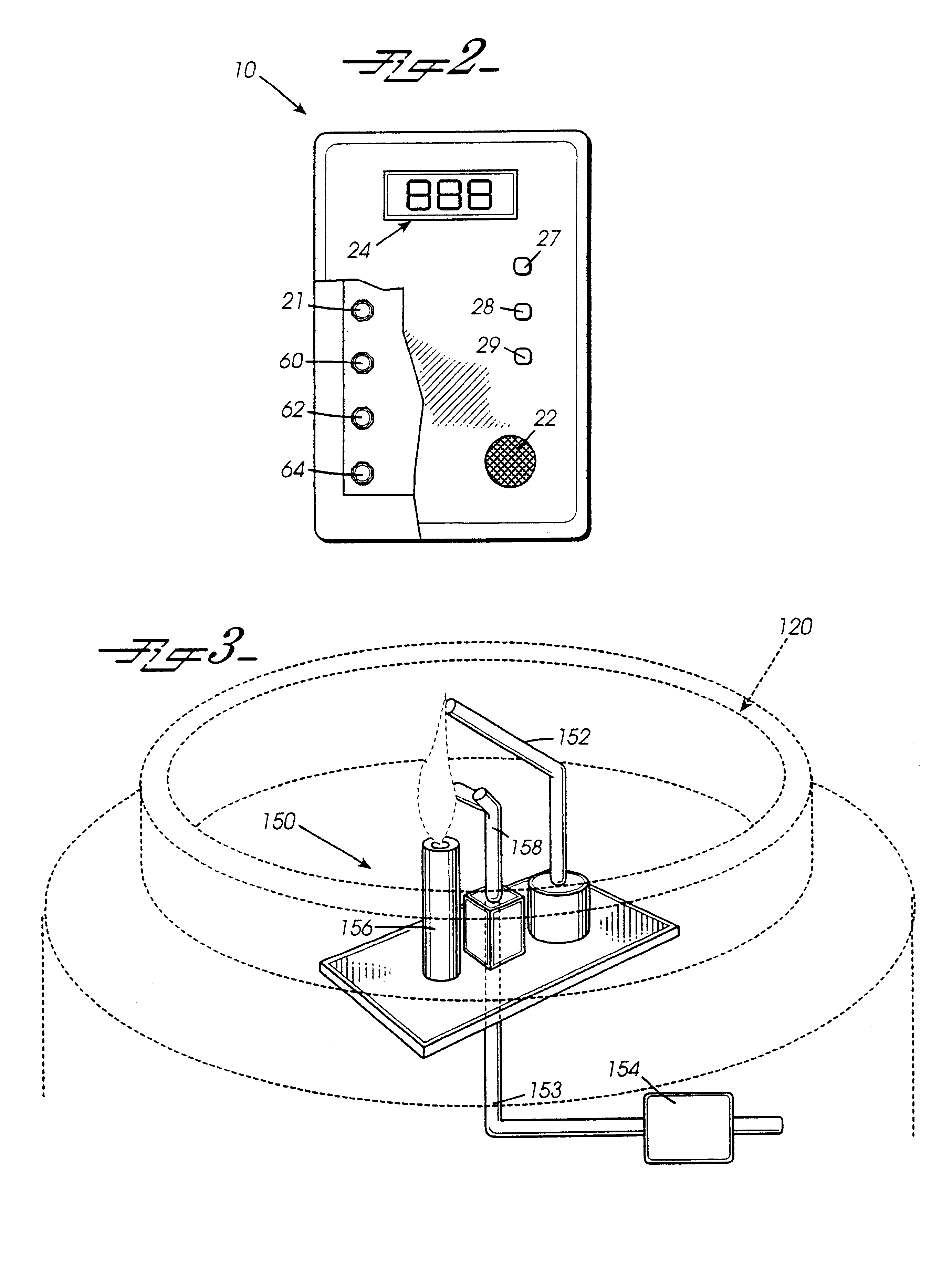
Referring now to the FIGS. 1 and 2, there is shown a partial cross-sectional side view and a partial cut away front view, respectively, of a multi-function controller according to a preferred embodiment of the present invention, designated generally by reference numeral 10.

Water heater 100 is comprised of a tank 110 dimensioned to hold a quantity of water therein. Disposed about the bottom of heater 100 is a series of combustion burners 120. In fluid communication with burners 120 are flue baffles 125 positioned inside flues 130. Both baffles 125 and flues 130 are positioned vertically within the interior of tank 110. Positioned atop heater 100 is a draft hood 136 in fluid communication with flues 130. Within draft hood 136 is a damper 140 controlled by a motor 142. Extending from draft hood 136 is a vent pipe 146....


PUM


Abstract

A multi-function controller for a water heater is advanced comprising a control panel and a plurality of sensors that monitor a variety of functions that impact the operation of a water heater. A flammable gas sensor, placed in proximity to the air intake, detects the presence of an unsafe concentration of gas and issues a signal to the control panel, which subsequently discontinues the operation of the burners. Detection of a blocked vent pipe is achieved by a carbon monoxide sensor placed near the draft hood. The control panel is equipped with circuitry which monitors usage of the heater for a specified time period to develop a pattern of use. Subsequent to the monitoring period, the controller will activate the burners a predetermined time prior to an anticipated period of high use. During periods of low use, the controller will decrease the temperature to which the water is to be heated, thereby resulting in a more efficient heater. Non-volatile memory records data from the sensors so that the operation status of the heater may be ascertained subsequent to a power outage. The control panel contains a plurality of visual alarms, each of which corresponds to a sensor. Consequently, repair and maintenance are simplified because the cause of a malfunction is quickly recognized.

Description

BACKGROUND OF THE INVENTION1. Field of the InventionThe present invention relates generally to water heaters. In particular, the present invention relates to the control of water heaters for proper operation and safety.2. Discussion of BackgroundMuch of the world has come to depend on having hot water on demand for bathing, laundering, and cooking. Usually this demand is met by water heaters. Water heaters come in two basic types: storage water heaters, which heat water in a tank for use when there is a demand, and instantaneous water heaters, which heat water as it is being drawn through the heater.Controlling the water heater begins with the temperature of the water it supplies. More specifically, being able to heat the source water to a desired temperature means being able to select that temperature from a range of temperatures and then controlling the water heater so that it does, in fact, heat the water to that temperature, regardless of changes in the many parameters that will...

Claims


Application Information

Patent Timeline
Patent Type & Authority Patents(United States)
IPC IPC(8): F24H9/20F24H1/20
CPCF23M2900/11021F24H1/205F24H9/2035F24H15/33F24H15/36F24H15/414F24H15/223F24H15/395F24H15/20F24H15/104F24H15/174
Inventor BRANDT, JOHN H.MEYER, RANDALL T.PLANK, BRADLEY N.
Owner AOS HLDG CO
Why Eureka
Try Eureka