Real-time hdr video for vehicle control

Active Publication Date: 2018-02-15
CONTRAST INC
View PDF3 Cites 56 Cited by
  • Summary
  • Abstract
  • Description
  • Claims
  • Application Information

AI Technical Summary

Benefits of technology

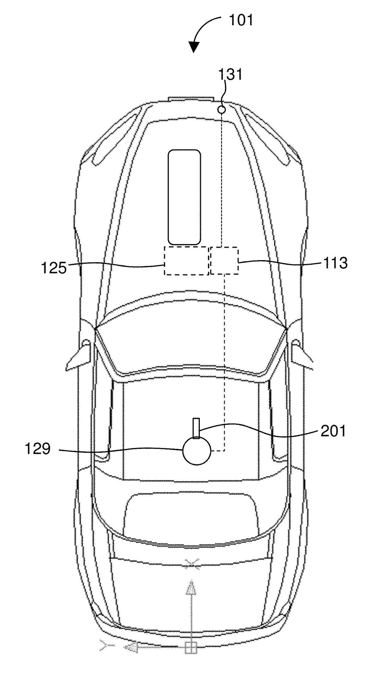
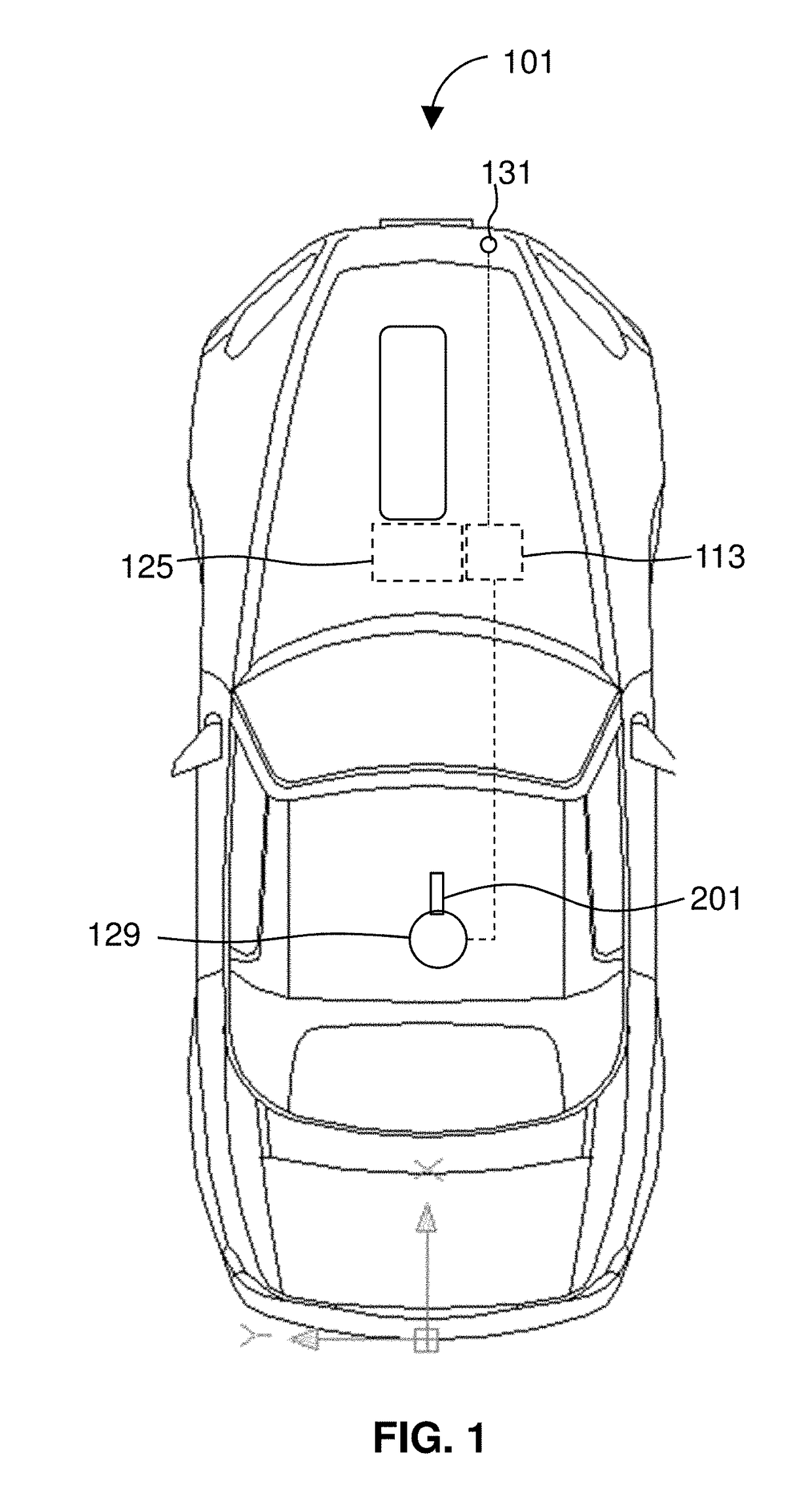
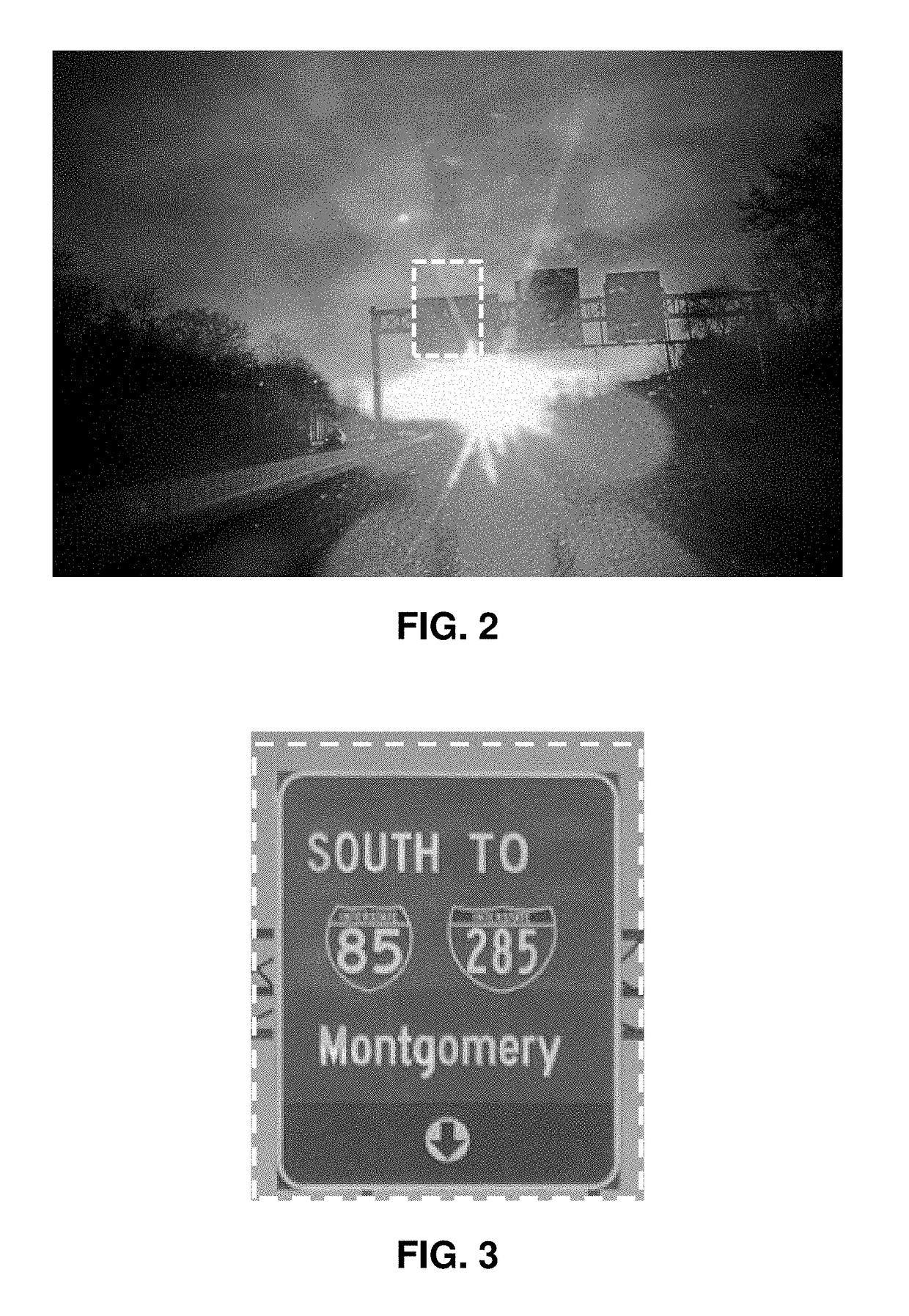
[0008]The HDR system offers functionality that may be employed in fully autonomous vehicles, as part of a driver assistance feature, or to provide accessory functionality outside of the primary driving functions, such as by augmenting a vehicle's navigational, safety, or entertainment systems. The HDR system may read lane markings and assist in keeping a vehicle in-lane. The system may, for example, use an HDR camera to read street signs or other landmarks to provide navigational assistance. Additionally or alternatively, the HDR camera may be used to detect and interpret road conditions such as dips, bumps, potholes, construction, metal plates, etc., and set up a car's electronic suspension damping for such features. The system may use one or more HDR cameras to collect information and feed the information to a server for, for example, a larger cartographical projects, such as building a road and business database for a navigational or emergency service system. In preferred embodiments, the HDR camera-based system is used to improve the utility and safety of fully autonomous vehicles. As discussed in greater detail herein, a fully autonomous vehicle can use the HDR video camera-based system to fully see and interpret all manner of detail in the road and environment, providing for optimized safety and efficiency in operation.
[0009]The HDR system may be provided as part of, or for use in, an automobile, such as a consumer's “daily driver” or in a ride-sharing or rental car. Such a vehicle will typically have 2 to 7 seats and a form factor

Problems solved by technology

Because the dynamic range is high, the vehicle detects dim, hard to discern features, even if a scene is dominated by bright light such as oncoming vehicle h

Method used


Image

  • Real-time hdr video for vehicle control
  • Real-time hdr video for vehicle control
  • Real-time hdr video for vehicle control

Examples


embodiment 201

[0075]This beamsplitter arrangement makes the HDR camera 201 light efficient: a negligible 0.04% of the total light gathered by the lens 311 is wasted. It also allows all three sensors to “see” the same scene, so all three images are optically identical except for their light levels. Of course, in the apparatus of the depicted embodiment 201, the ME image has undergone an odd number of reflections and so it is flipped left-right compared to the other images, but this is fixed easily in software. In preferred embodiments, the three sensors independently stream incoming pixel values directly into a pipeline that includes a synchronization module. This synchronization module can correct small phase discrepancies in data arrival times to the system from multiple sensors.

[0076]Thus it can be seen that the beamsplitter 301 directs a majority of the light to the first path and a lesser amount of the light to the second path. Preferably, the first path and the second path impinge on the HE ...

case 1

[0107] The pixel 615 is not saturated and the neighborhood 601 has no saturated pixels, so the pixel value is used as-is.

case 2

[0108] The pixel 615 is not saturated, but the neighborhood 601 has 1 or more saturated pixels, so blend between the pixel value at IHE(x, y) and the one at the next darker-exposure IME(x, y) depending on the amount of saturation present in the neighborhood.


PUM


Abstract

The invention provides an autonomous vehicle with a video camera that merges images taken a different light levels by replacing saturated parts of an image with corresponding parts of a lower-light image to stream a video with a dynamic range that extends to include very low-light and very intensely lit parts of a scene. The high dynamic range (HDR) camera streams the HDR video to a HDR system in real time—as the vehicle operates. As pixel values are provided by the camera's image sensors, those values are streamed directly through a pipeline processing operation and on to the HDR system without any requirement to wait and collect entire images, or frames, before using the video information.

Description

CROSS-REFERENCE TO RELATED APPLICATION[0001]This application claims priority to U.S. Provisional Application Ser. No. 62 / 372,527, filed Aug. 9, 2016, the contents of which is incorporated by reference.TECHNICAL FIELD The invention relates to systems for autonomous vehicles.BACKGROUND[0002]A number of companies have manufactured autonomous (i.e., self-driving) vehicles. The state of Nevada has declared that self-driving cars and trucks may legally use the roads. It is possible that other states will follow Nevada's lead and allow any number of autonomous taxis, tractor-trailers, private luxury cars, and other such vehicles onto the roads.[0003]Unfortunately, autonomous vehicles are subject to many of the same limitations as traditional cars. For example, even if a vehicle is driven carefully, there is a risk of an accident that comes with driving in an unpredictable environment. Additionally, physical limits such as visibility or traction apply to autonomous vehicles just as to tradi...

Claims


Application Information

Patent Timeline
IPC IPC(8): H04N5/235H04N5/225B60R1/00H04N9/73H04N9/07G02B27/10H04N5/232G06K9/00
CPCH04N5/2355H04N5/23238H04N5/2258G06K9/00805H04N9/735H04N9/07G02B27/106B60R1/00G06T1/20G06K9/00818G05D1/0246B60R2300/102B60R2300/30H04N9/67H04N9/76G02B27/1066G02B27/144G06V20/582G06V20/58H04N23/45H04N23/57H04N23/698H04N23/741H04N23/10H04N23/12H04N23/88
Inventor KISER, WILLIE C.TOCCI, NORATOCCI, MICHAEL D.
Owner CONTRAST INC
Why Eureka
Try Eureka