Apparatus and Method for Controlling the Secondary Injection of Fuel

a gas turbine engine and fuel injection technology, applied in the direction of combustion control, machines/engines, lighting and heating apparatus, etc., can solve the problems of unburned hydrocarbons, increased carbon monoxide and unburned hydrocarbons, and inability to achieve balan

Active Publication Date: 2009-04-02
SIEMENS ENERGY INC
View PDF29 Cites 141 Cited by
  • Summary
  • Abstract
  • Description
  • Claims
  • Application Information

AI Technical Summary

Problems solved by technology

One challenge in such single site injection systems is there is always a balance to be obtained between the combustion temperature and the efficiency of the combustor.
The cooler peripheral areas have decreased combustion efficiency and increased levels of carbon monoxide and unburned hydrocarbons.

Method used


Image

  • Apparatus and Method for Controlling the Secondary Injection of Fuel
  • Apparatus and Method for Controlling the Secondary Injection of Fuel
  • Apparatus and Method for Controlling the Secondary Injection of Fuel

Examples


Embodiment Construction

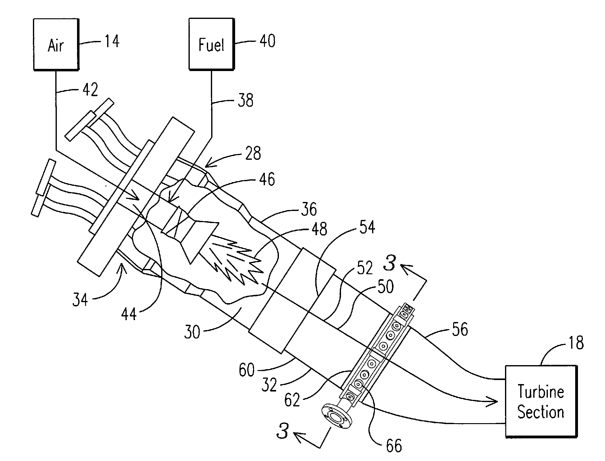
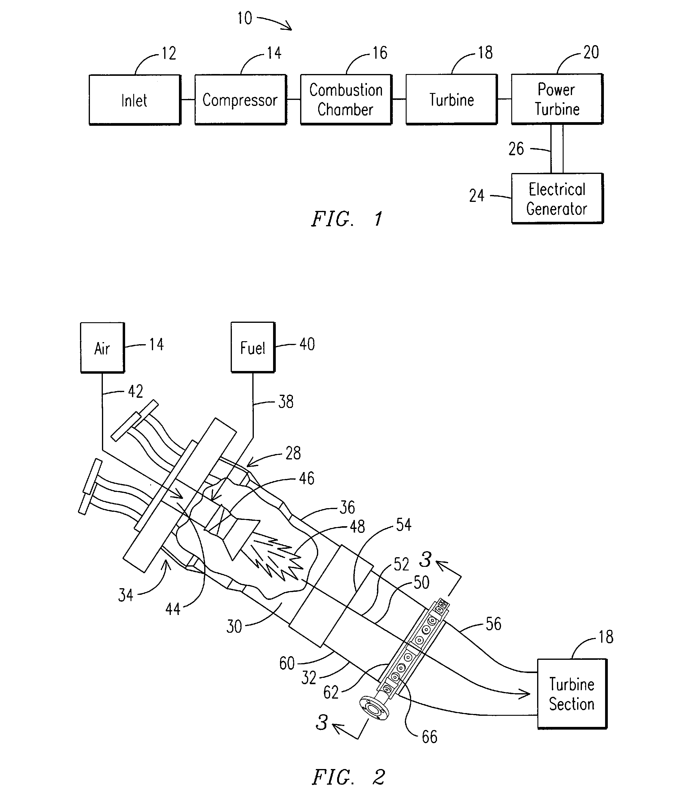
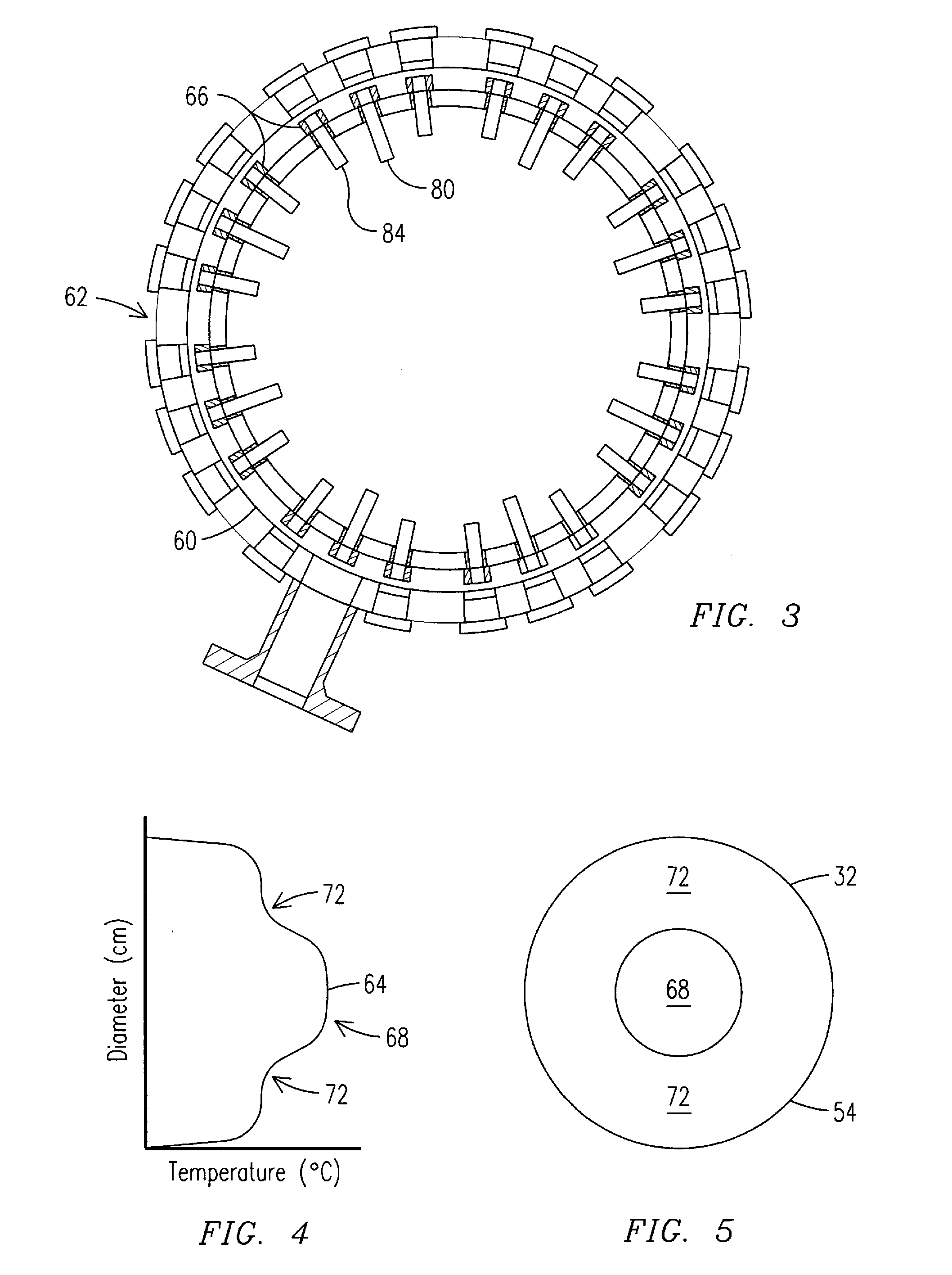
[0025]In accordance with one aspect of the present invention, the inventors of the present invention have developed novel apparatus and methods for reducing levels of NOx, carbon monoxide and unburned hydrocarbons in exhaust gases while increasing the efficiency of combustors. The apparatus and methods of the present invention inject a first fuel into a compressed air stream flowing through the primary combustion chamber and through the transition piece to create a combustion stream having a radial temperature profile at an inlet of the transition piece. In one aspect of the present invention, there is provided apparatus and methods for differentially injecting a second fuel into the combustion stream within the transition piece. By injecting the second fuel in accordance with the present invention in the transition piece, combustion is evened out and the temperature profile of the combustion stream is smoothed prior to an end of the transition piece. In addition, levels of NOx, car...


PUM


Abstract

In one embodiment, a combustor (28) for a gas turbine engine is provided comprising a primary combustion chamber (30) for combusting a first fuel to form a combustion flow stream (50) and a transition piece (32) located downstream from the primary combustion chamber (30). The transition piece (32) comprises a plurality of injectors (66) located around a circumference of the transition piece (32) for injecting a second fuel into the combustion flow stream (50). The injectors (66) are effective to create a radial temperature profile (74) at an exit (58) of the transition piece (32) having a reduced coefficient of variation relative to a radial temperature profile (64) at an inlet (54) of the transition piece (32). Methods for controlling the temperature profile of a secondary injection are also provided.

Description

[0001]This application claims benefit under 35 USC 119(e)(1) of the Sep. 14, 2007 filing date of U.S. Provisional Application Nos. 60 / 972,405 and 60 / 972,395, the entirety of each of which are incorporated by reference herein.STATEMENT REGARDING FEDERALLY SPONSORED DEVELOPMENT[0002]Development for this invention was supported in part by Contract No. DE-FC26-05NT42644, awarded by the United States Department of Energy. Accordingly, the United States Government may have certain rights in this invention.FIELD OF THE INVENTION[0003]The present invention relates to an apparatus and method for operating a gas turbine engine, and more particularly to an apparatus and a method for controlling the secondary injection of fuel to provide an increasingly even temperature distribution for the combustion of fuel, thereby reducing an amount of NOx, unburned hydrocarbons, and carbon monoxide in the exhaust gas traveling from the transition piece to a first set of turbine blades in a gas turbine engi...

Claims


Application Information

Patent Timeline
Patent Type & Authority Applications(United States)
IPC IPC(8): F02C9/40F02C3/20
CPCF01D9/023F02C3/14F02C7/222F23D2900/14004F23R3/346F23N1/002F23N2025/14F23N2037/02F23N2041/20F23K5/10F23N2225/14F23N2237/02F23N2241/20
Inventor MARTIN, SCOTT M.CAI, WEIDONGHARRIS, JR., ARTHUR J.
Owner SIEMENS ENERGY INC
Why Eureka
Try Eureka