Method for dressing of a grinding worm by means of a dressing roll and dressing roll

a dressing roll and grinding worm technology, applied in the direction of gear teeth, gear teeth, gear-teeth manufacturing apparatus, etc., can solve the problem of not being desired

Active Publication Date: 2020-10-13
KAPP WERKZEUGMASCH +1
View PDF22 Cites 0 Cited by
  • Summary
  • Abstract
  • Description
  • Claims
  • Application Information

AI Technical Summary

Benefits of technology

[0023]It is the object of the invention to further develop a generic method in such a manner and to provide a respective dressing roll by which it is possible to selectively influence the surface roughness of the ground tooth flank along the tooth height, which should be reached by selectively influencing the employed material part of the abrasive material along the height of the flank of the dressing roll.
[0030]Thus, the present invention provides a method for the production of a dressing roll and a dressing roll to dress with the same a dressable grinding worm in such a manner that with the same the creation of a variable surface roughness along the height of a tooth of a gear-shaped workpiece becomes possible.
[0031]Thereby it becomes possible to provide a tool (dressing roll) for dressing of a dressable grinding worm with a variable material part along the height of the flank so that also the dressable grinding worm is created with a variable material part along the height of the flank and by doing so then furthermore a variable surface roughness along the height of the tooth of the workpiece which has to be ground can be produced.
[0034]At the design of the tooth-shaped surface of the counterpart for the production of the dressing roll thus a willful “wrong” tool profile is used as basis. After the production of the base body with a layer of abrasive particles (i.e. especially with boron nitride (CBN) or diamond grains of equal size and / or granularity) the dressing tool (dressing roll) is reworked as described with a (diamond) grinding wheel. But the rework does not take place with an equal distance between the profile of the tooth-shaped surface (of the counterpart) and the abrasive profile which has to be created, but according to be “right” given profile. Thus, at the end of the process no constant (equidistant) amount is removed from the abrasive particles along the height of the tooth, rather the removed amount is changing along the radial height of the abrasive profile. Basing on the effect that all abrasive grains which form the layer on the base body have the same grain size, i.e. about the same dimension, the single abrasive grains are accordingly removed differently during the rework.

Problems solved by technology

However, this is not desired in each case.

Method used


Image

  • Method for dressing of a grinding worm by means of a dressing roll and dressing roll
  • Method for dressing of a grinding worm by means of a dressing roll and dressing roll
  • Method for dressing of a grinding worm by means of a dressing roll and dressing roll

Examples


Embodiment Construction

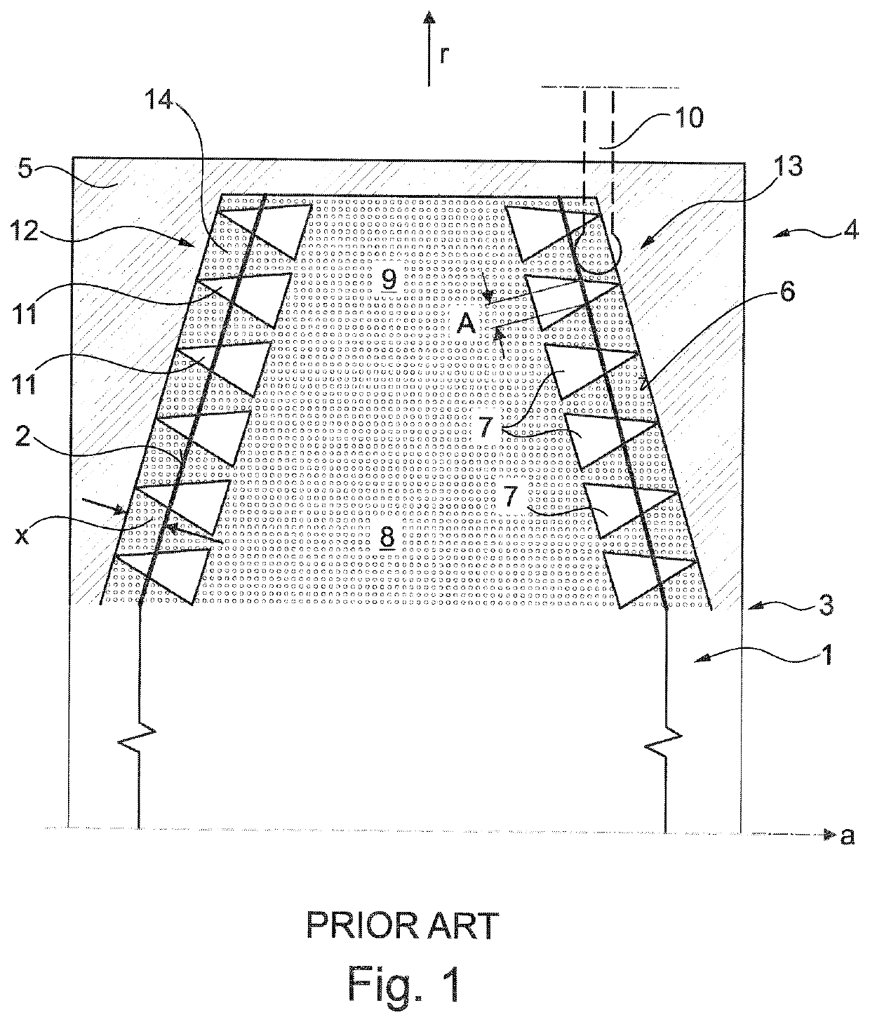
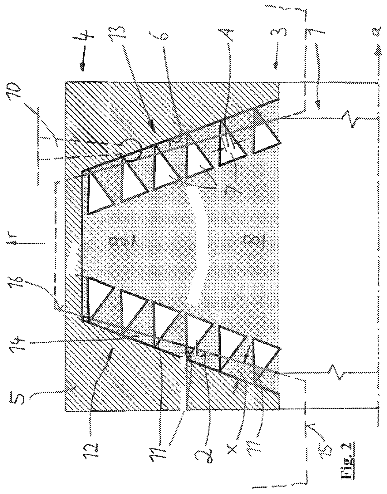
[0047]The principle of the present invention can be described by comparing FIG. 1 (solution according to the state of the art) and FIG. 2 (embodiment according to the invention):

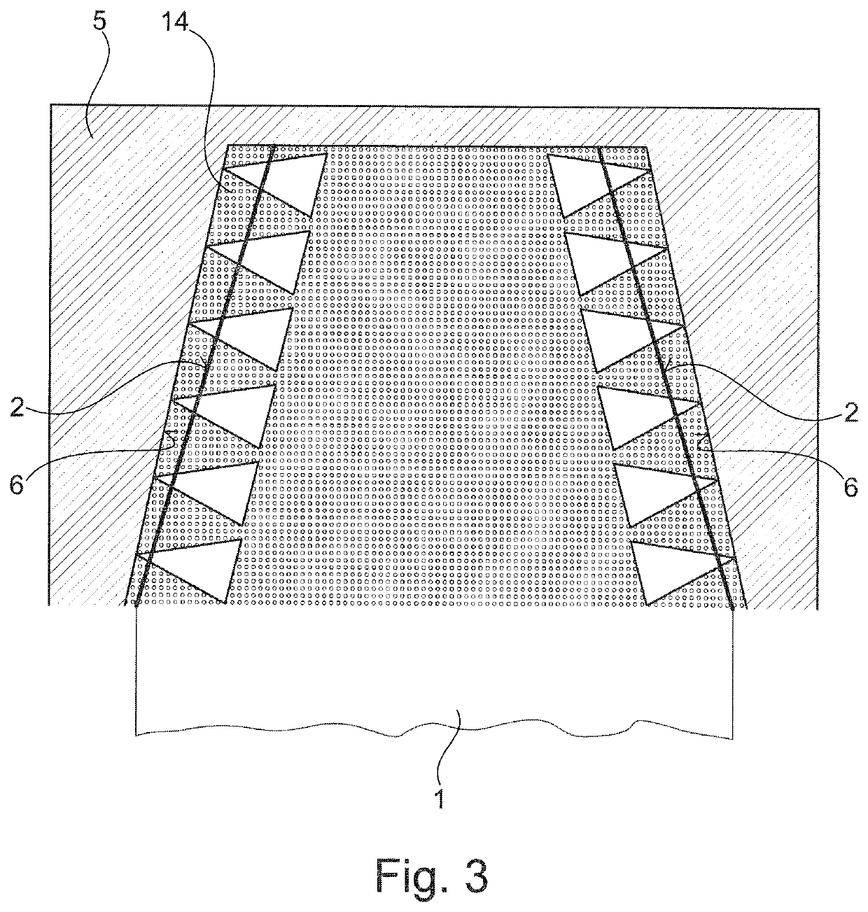
[0048]At first a counterpart 5 with an inner (hollow) space 9 is provided, wherein the space 9 is delimited by a tooth-shaped surface 6. However, the tooth-shaped surface 6 thereby corresponds not exactly to the later desired abrasive profile 2 of the dressing roll 1. The surface 6 which extends in radial direction r from a root region 3 to a tip region 4 is provided with abrasive particles 7 and said particles are fixed on the surface 6 (for example by a galvanically or chemically deposited nickel layer). The fixation takes place by means of a carrier layer 14, in the embodiments made from nickel. The single abrasive particles 7 have substantially the same size and form consequently a layer with constant thickness on the surface 6.

[0049]Then, the base body of the dressing roll is produced, namely by machini...


PUM

PropertyMeasurementUnit
abrasiveaaaaaaaaaa
distanceaaaaaaaaaa
surface structureaaaaaaaaaa

Abstract

A method for dressing a grinding worm using a dressing roll that engages the grinding worm to profile its helical grinding profile. The abrasive profile of the dressing roll is at least partially tooth-shaped in a radial cross section and extends radially from a root region to a tip region. The dressing roll is produced by: a) producing a counterpart having an inner surface; b) positioning and fixing a layer of abrasive particles on the tooth-shaped surface; c) producing a disk-shaped base body of the dressing roll and connecting the base body with a carrier layer for the abrasive particles; d) demolding the base body; e) profiling the base body. Step a) includes providing the counterpart with the surface so that the distance between the profiled surface and the abrasive profile changes during advancing from the root region to the tip region at least at one flank of the surface, measured in the radial cross section perpendicular to the profiled surface.

Description

CROSS-REFERENCE TO RELATED APPLICATIONS[0001]The present application claims priority of DE 10 2016 014 180.8, filed Nov. 28, 2016, the priority of this application is hereby claimed and this application is incorporated herein by reference.BACKGROUND OF THE INVENTION[0002]The invention relates to a method for dressing of a grinding worm by means of a dressing roll in which the dressing roll, which is provided with an abrasive profile, is brought into engagement with the grinding worm to profile its helical grinding profile, wherein the abrasive profile of the dressing roll is at least partially designed tooth-shaped in a radial cross section and extends radially from a root region to a tip region, wherein the dressing roll is produced by the steps:[0003]a) Producing of a counterpart (negative form) which has an inner surface which is at least partially tooth-shaped in the radial cross section;[0004]b) Positioning of a layer of abrasive particles on the tooth-shaped surface and fixing...

Claims


Application Information

Patent Timeline
Patent Type & Authority Patents(United States)
IPC IPC(8): B24B53/075B24B53/053B23F23/12B23F5/04B23F21/02B23F13/04B24B53/12B24B53/017B24B53/14B24D18/00
CPCB24B53/075B24D18/00B24B53/017B24D18/0018B24B53/14B23F23/1225B24B53/053B23F5/04B23F21/02B23F13/04B24B53/12B24D18/0009B24B53/07
Inventor GRINKO, SERGIY
Owner KAPP WERKZEUGMASCH
Why Eureka
Try Eureka