Fixing structure for protective cover of valve assembly

a technology of fixing structure and valve assembly, which is applied in the direction of valve housing, heating type, lighting and heating apparatus, etc., can solve the problems of troublesome water leakage test, measurement inconvenience and errors

Active Publication Date: 2020-10-13
GLOBE UNION INDAL
View PDF14 Cites 0 Cited by
  • Summary
  • Abstract
  • Description
  • Claims
  • Application Information

AI Technical Summary

Benefits of technology

[0008]The primary aspect of the present invention is to provide a fixing structure for a protective cover of a valve assembly which connects or removes the protective cover with or from the body easily and quickly.
[0009]Another aspect of the present invention is to provide a fixing structure for a protective cover of a valve assembly which avoid fixes the protective cover incorrectly so as to facilitate installation and depth adjustment.

Problems solved by technology

To preserve the depth, a height of the protective cover higher than the basic wall is measured by a ruler or other measurement tools, when the valve assembly is locked on a wooden rack in the basic wall, thus causing measurement inconvenience and errors.
Thereafter, the protective cover is connected with the holder by screwing the screw bolts via the holder and the protective cover, after testing the water leakage and detaching the testing lid, thus having troublesome test of the water leakage.

Method used


Image

  • Fixing structure for protective cover of valve assembly
  • Fixing structure for protective cover of valve assembly
  • Fixing structure for protective cover of valve assembly

Examples


Embodiment Construction

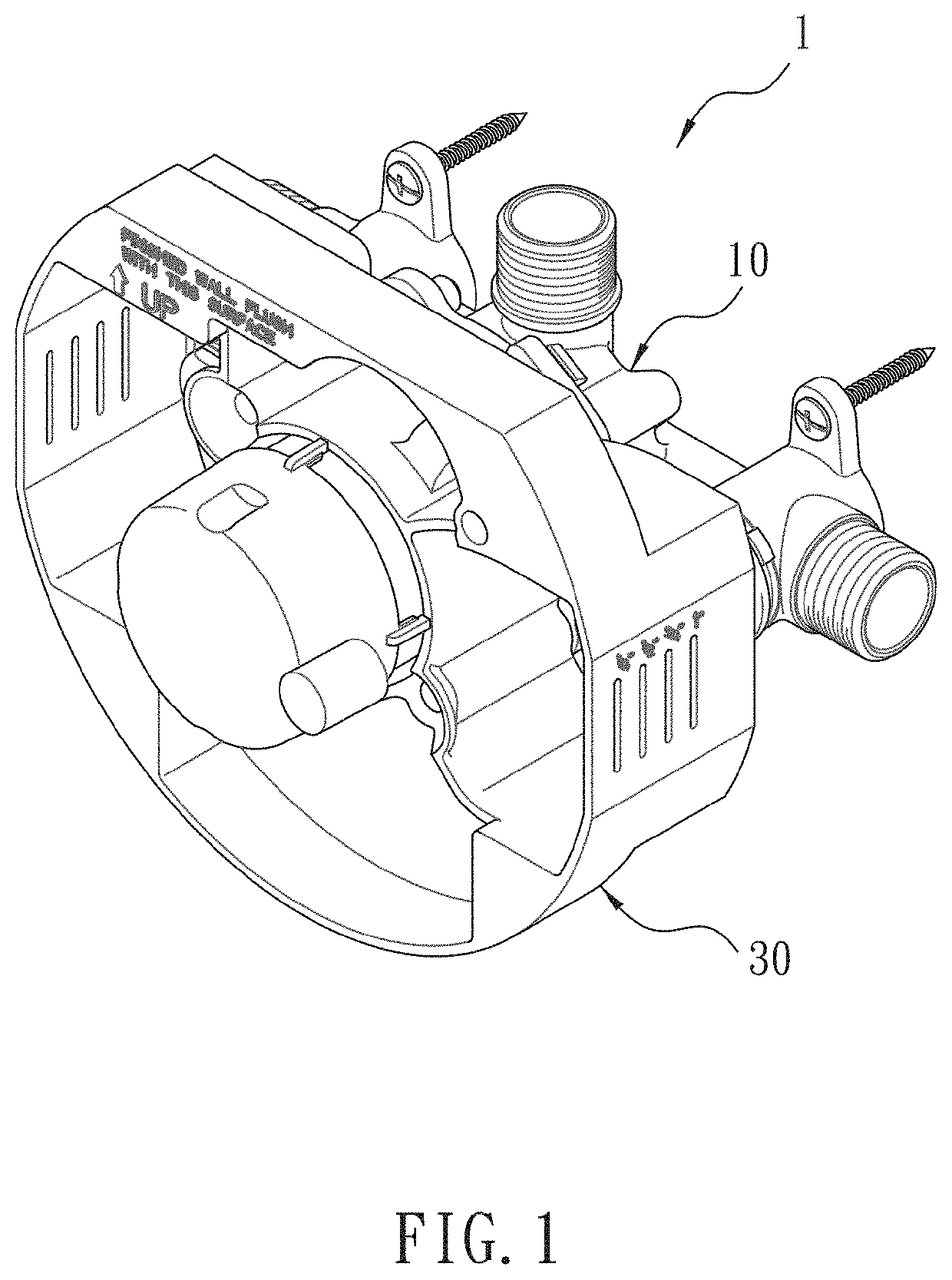
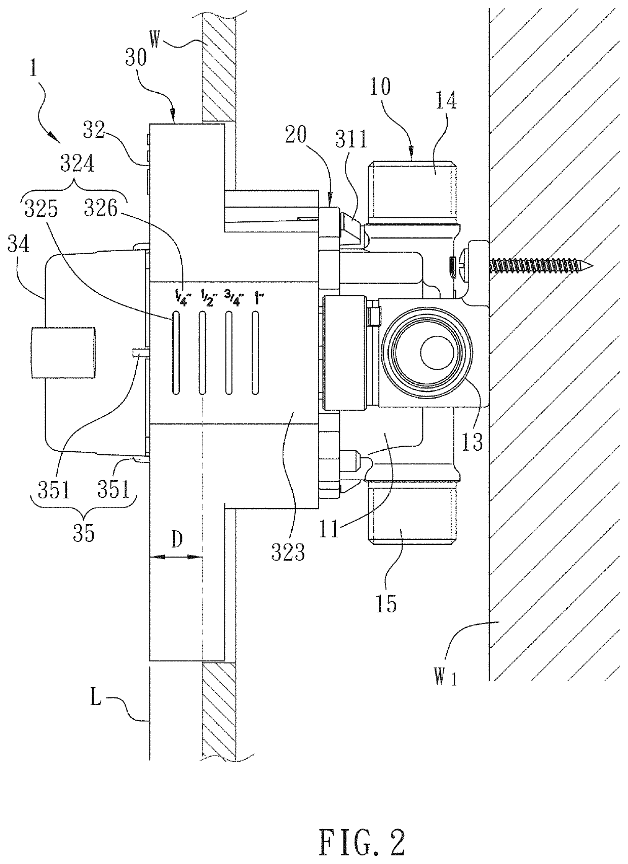
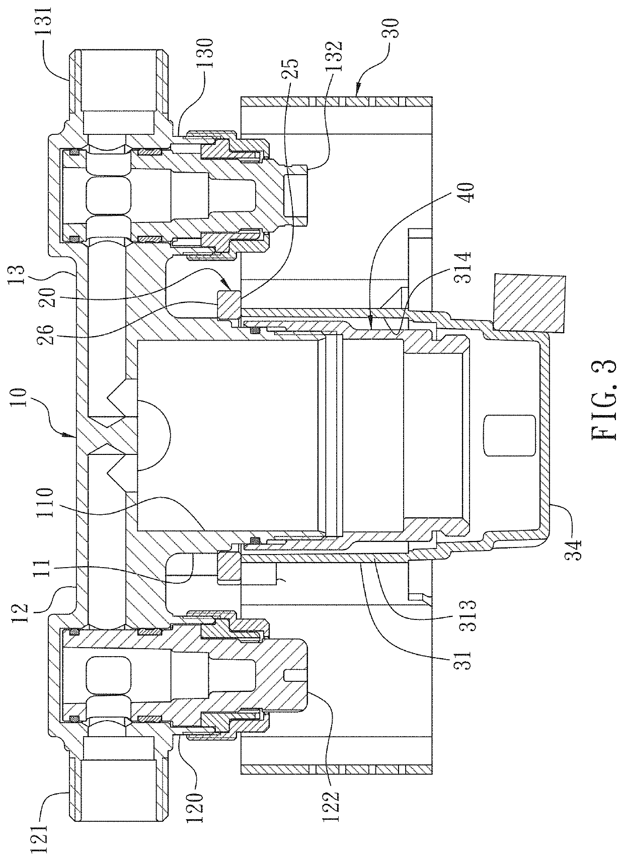
[0028]With reference to FIGS. 1-4, a fixing structure for a protective cover 30 of a valve assembly 1 according to a preferred embodiment of the present invention comprises: a body 10, a positioning plate 20, and the protective cover 30.

[0029]The body 10 is mounted in a basic wall W, such as a wooden rack W1 housed in the basic wall W. As shown in FIG. 5, the body 10 includes a holder 11, wherein the holder 11 includes a cold-water inflow connector 12 horizontally extending from a first side thereof, a hot-water inflow connector 13 horizontally extending from a second side of the holder 11 opposite to the cold-water inflow connector 12, a first outflow connector 14 vertically extending from a top of the holder 11, and a second outflow connector 15 vertically extending from a bottom of the holder 11 opposite to the first outflow connector 14; the cold-water inflow connector 12 has a cold-water inflow seat 121 configured to connect with a cold-water inflow pipe 2, and the hot-water in...


PUM


Abstract

A valve assembly capable of indicating a depth contains: a body includes a holder. The holder includes a cold-water inflow connector, a hot-water inflow connector, a first outflow connector, and a second outflow connector. The cold-water inflow connector has a cold-water inflow seat configured to connect with a cold-water inflow pipe, and the hot-water inflow connector has a hot-water inflow seat configured to connect with a hot-water inflow pipe. The holder further includes a first coupling portion and a second coupling portion. The positioning plate includes the opening for fitting with the holder, a first fixing portion formed around the opening, a second fixing portion formed around the opening, and at least two recesses arranged around the opening, wherein the first fixing portion is configured to connect with the first coupling portion, and the second fixing portion is configured to couple with the second coupling portion.

Description

FIELD OF THE INVENTION[0001]The present invention relates to a temperature control valve or a thermostatic valve of bathroom equipment, and more particularly to a fixing structure for a protective cover of a valve assembly.BACKGROUND OF THE INVENTION[0002]A temperature control valve or a thermostatic valve assembly of bathroom equipment is employed to adjust or set a temperature of a water supply. A conventional valve assembly is mounted on a wall of a bathroom and contains a body on which a holder is formed. The holder includes an accommodation chamber configured to accommodate a mixing valve covered by a decoration cover, and the holder includes a control bar for controlling the mixing valve. The holder includes a cold-water inflow connector horizontally extending from a first side thereof, a hot-water inflow connector horizontally extending from a second side of the holder opposite to the cold-water inflow connector, a first outflow connector, and a second outflow connector. Ther...

Claims


Application Information

Patent Timeline
Patent Type & Authority Patents(United States)
IPC IPC(8): F16K27/12E03C1/04F24D19/10F16K27/02E03C1/02
CPCF16K27/0263E03C1/023E03C1/0404F16K27/12F24D2220/0242F24D19/1015F24D2220/0257F16K19/006
Inventor CHANG, TACHUNXIAO, YUEPINGHE, KAIZHONG
Owner GLOBE UNION INDAL
Why Eureka
Try Eureka