
Fixed-wing flying device configured to fly in multiple directions

a fixed-wing configuration, flying device technology, applied in the direction of gliders, wing shapes, vehicles, etc., can solve the problems of complicated stability, difficult for a fixed-wing configuration airplane to have a steady glide ratio, and only effective for one exact steady glid

Active Publication Date: 2020-10-27
ZONGKER JAMES DEAN
View PDF17 Cites 3 Cited by
  • Summary
  • Abstract
  • Description
  • Claims
  • Application Information

AI Technical Summary

Benefits of technology

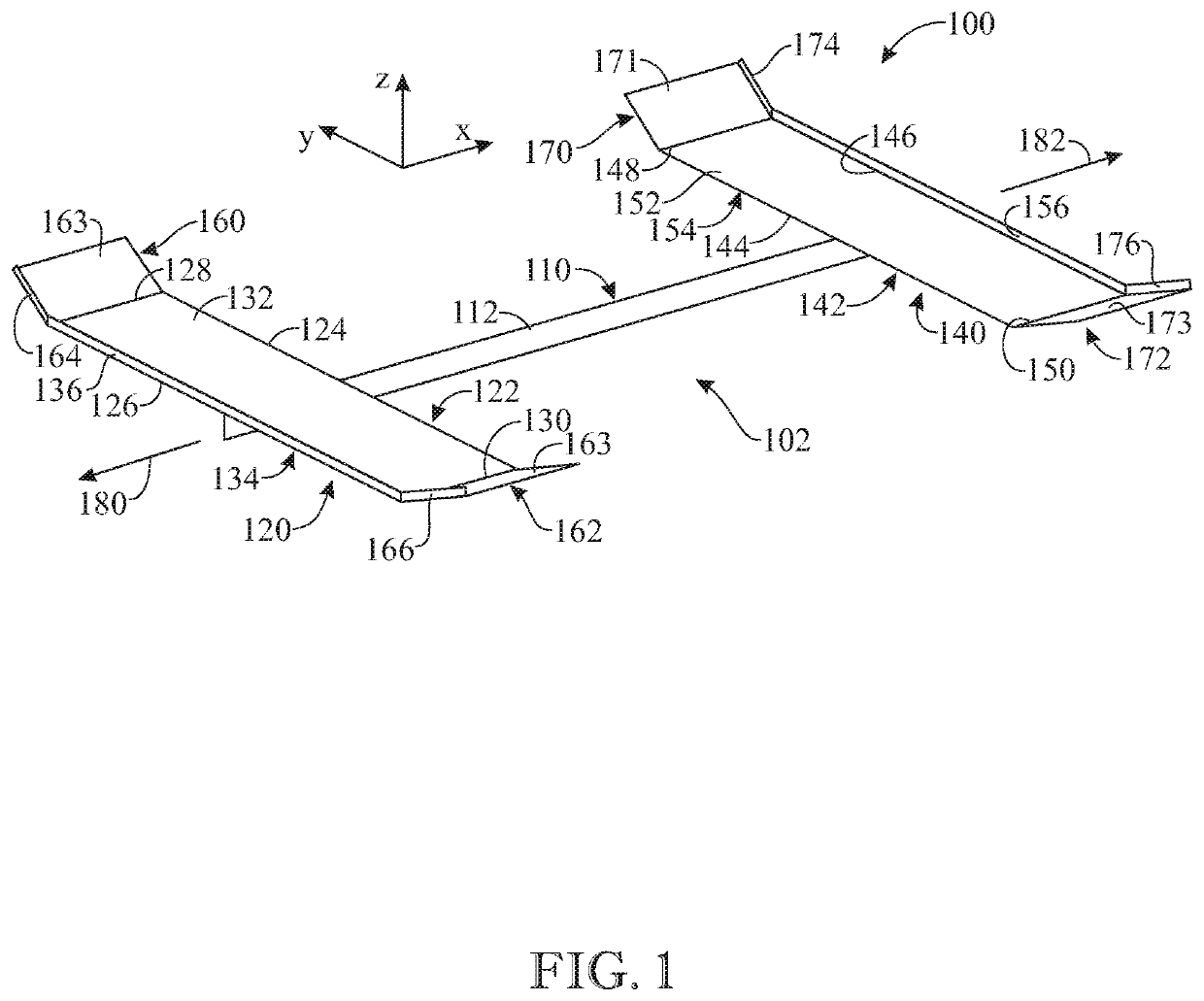
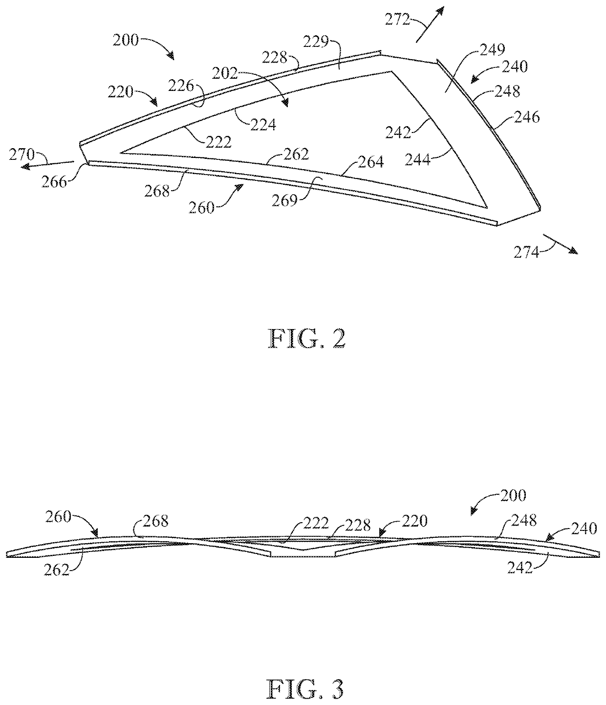
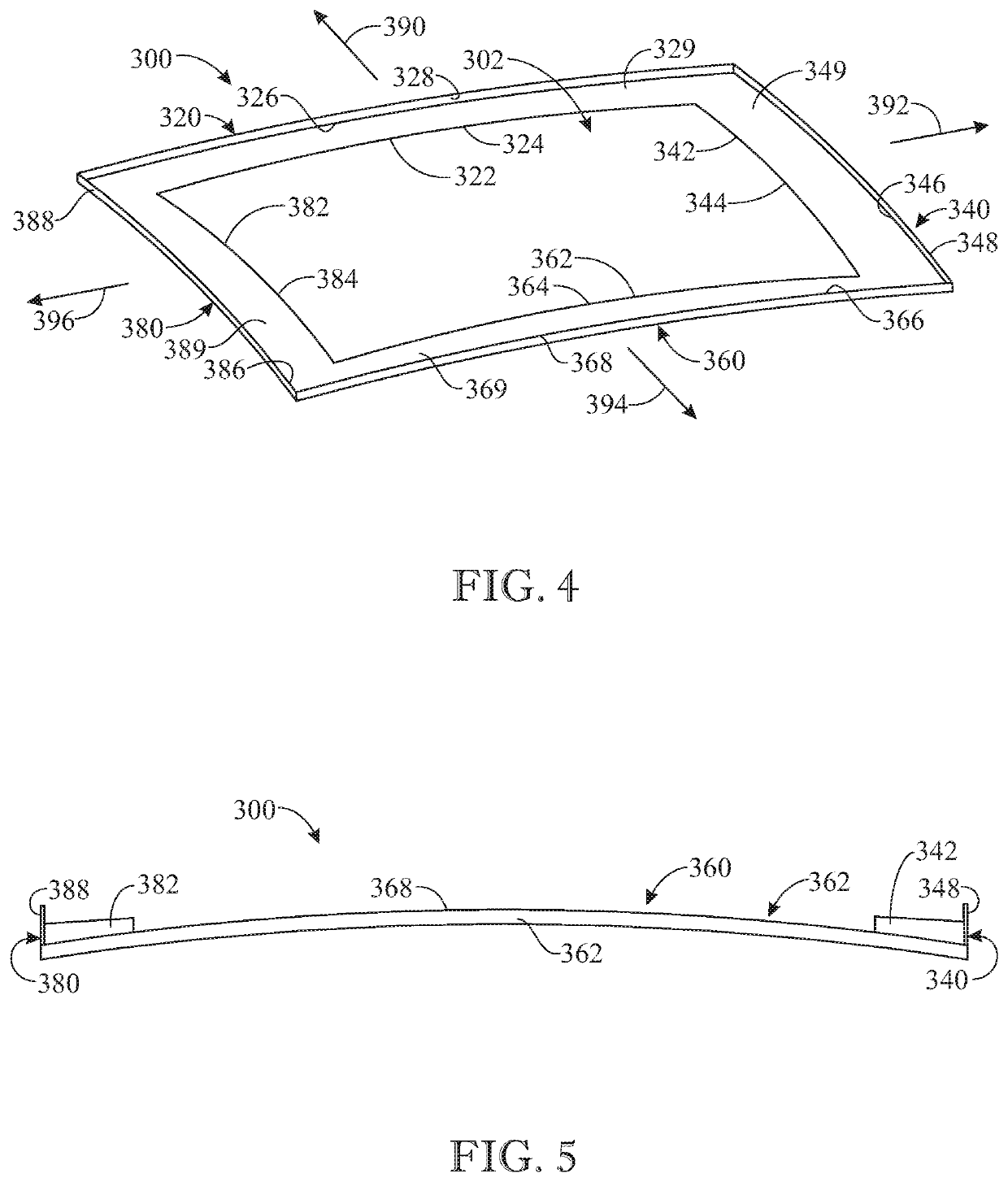
The present invention is a fixed-wing flying device that can fly in multiple directions without needing to adjust its center of gravity or trim. It has multiple non-rotating wings that have a protruding wall along their outer edge. This design allows the device to exhibit speed-seeking glide capability in more than one flight direction by using an air dam or wall at the edge of each wing to disrupt airflow and shift lift to or very near the center of gravity. This configuration provides a more efficient and stable means of flying in multiple directions without needing to adjust its center of gravity or trim.

Problems solved by technology

This makes it difficult for a fixed-wing configuration airplane to have a steady glide ratio in directions other than a frontward direction (for example, backwards or sideways) and can complicate stability while flying at extreme yaw or sideslip angles.
However, this solution is only effective for one exact steady glide speed.
Two identical wings set far apart along a fuselage can almost glide in either direction, but do not quite attain speed-seeking stability because their lift is centered slightly forward of the center of the craft.

Method used


Image

  • Fixed-wing flying device configured to fly in multiple directions
  • Fixed-wing flying device configured to fly in multiple directions
  • Fixed-wing flying device configured to fly in multiple directions

Examples


Embodiment Construction

[0041]The following detailed description is merely exemplary in nature and is not intended to limit the described embodiments or the application and uses of the described embodiments. As used herein, the word “exemplary” or “illustrative” means “serving as an example, instance, or illustration.” Any implementation described herein as “exemplary” or “illustrative” is not necessarily to be construed as preferred or advantageous over other implementations. All of the implementations described below are exemplary implementations provided to enable persons skilled in the art to make or use the embodiments of the disclosure and are not intended to limit the scope of the disclosure, which is defined by the claims. For purposes of description herein, the terms “upper”, “lower”, “left”, “rear”, “right”, “front”, “vertical”, “horizontal”, and derivatives thereof shall relate to the invention as oriented in FIG. 1. Furthermore, there is no intention to be bound by any expressed or implied theo...


PUM


Abstract

A fixed-wing flying apparatus, aircraft, airplane or device is provided which is capable of stably gliding in more than one direction such as backwards, frontward or sideways. The device comprises a plurality of wings arranged around the center of area and defining a space therebetween. Each wing includes an outwardly protruding wall along an outer edge of the wing, which disrupts airflow over the wing flying in front so it is less effective than the wing flying behind, facilitating temporary or long term sustainable speed-seeking glide stability in more than one forward direction without any trim or center of gravity adjustment. The plurality of wings can include two wings, three wings forming a triangle, or four wings forming a square or rectangle. The aircraft can be unpowered, powered, free-flight or controlled. A one-front airplane can also be constructed with very relaxed yaw stability.

Description

CROSS-REFERENCE TO RELATED APPLICATIONS[0001]This application claims the benefit of U.S. Provisional Patent Application Ser. No. 62 / 419,768, filed on Nov. 9, 2016, which is incorporated by reference herein in its entirety.FIELD OF THE INVENTION[0002]The present invention relates generally to flying apparatus or devices, and more particularly, to a fixed-wing flying apparatus or device which is configured to fly in more than one direction by providing the flying device with two or more wings arranged in a spaced-apart configuration with one another and having a protruding wall extending from and along an outer edge of each wing.BACKGROUND OF THE INVENTION[0003]Heavier-than-air flying apparatus or devices, such as airplanes, are capable of overcoming their natural gravitational attraction to the Earth and flying in the air. For this purpose, such flying apparatus or devices are provided with fixed or moving wings of various designs. As known in aerodynamics, when such a flying apparat...

Claims


Application Information

Patent Timeline
Patent Type & Authority Patents(United States)
IPC IPC(8): B64C31/02B64C3/14B64C3/16B64C39/08
CPCB64C3/14B64C31/02B64C39/08B64C3/16B64C2003/146B64C3/10
Inventor ZONGKER, JAMES DEAN
Owner ZONGKER JAMES DEAN
Learn More