Sterile airflow delivery system

a delivery system and sterile technology, applied in ventilation systems, lighting and heating apparatus, heating types, etc., can solve the problems of increased patient vulnerability to pathogens transmitted by surgical personnel, extended hospital stays, extended post-operative recovery, etc., and achieves enhanced laminar effect and effective removal of contaminants

Inactive Publication Date: 2019-08-01
HAAR JONATHAN
View PDF0 Cites 12 Cited by
  • Summary
  • Abstract
  • Description
  • Claims
  • Application Information

AI Technical Summary

Benefits of technology

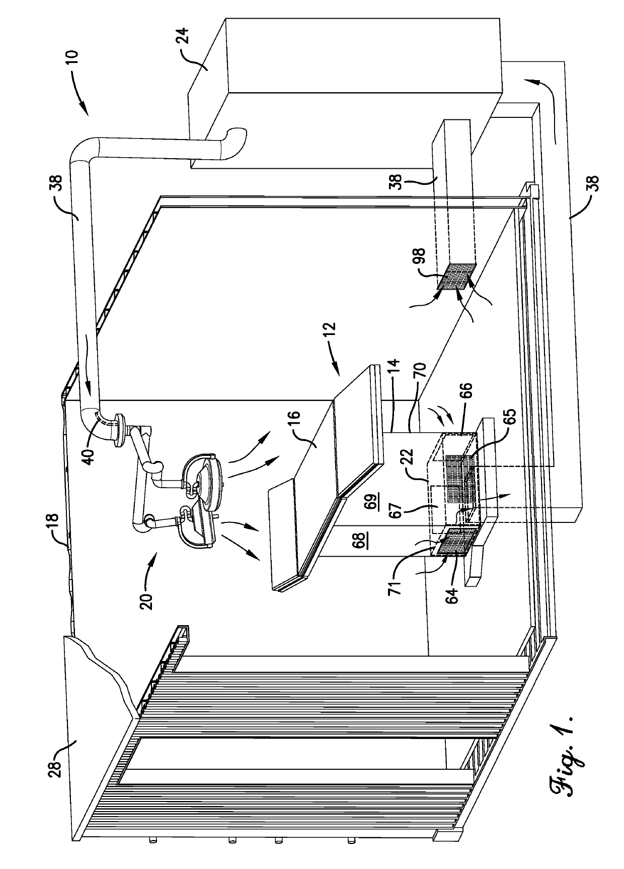
[0010]The return inlet is positioned on the base of the operating platform and is configured to receive airflow from around the operating platform. By being positioned on the base of the operating platform, the system is configured to provide laminar airflow across the operating platform, thereby more effectively removing contaminants, such as squames. Because the airflow is introduced in conjunction with lighting directly above the patient from the airflow delivery apparatus, the airflow is less likely to be obstructed. Thus, the airflow from the airflow delivery apparatus to the return inlet is more laminar and consistent.
[0011]The above-described system may also additionally or alternatively comprise a second airflow delivery apparatus positioned above the operating platform. The second airflow delivery apparatus includes a frame and a second plurality of vents. The frame is positioned above the operating platform and includes a channel for receiving airflow. The second plurality of vents is connected to the channel and configured to receive the airflow from the channel and direct the airflow toward a perimeter of the operating platform. The airflow from the frame toward the perimeter and to the return inlet acts as an air curtain surrounding the operating platform that prevents contaminates outside the perimeter of the operating platform from entering an operating field.
[0012]The above-described system may also comprise a second return inlet and a return plenum positioned in the base of the operating platform. The return plenum includes a duct, an inlet fan, a discharge outlet, and a particulate filter. The duct is connected to the return inlets. The inlet fan is positioned in the duct and configured to pull airflow into the duct through the return inlets. The discharge outlet is also connected to the duct. The filter is positioned between the discharge outlet and the return inlets so that the airflow from the return inlets to the discharge outlet is filtered. The return plenum enhances laminar airflow around the operating platform by not creating a pressure vacuum, which could disrupt the airflow.

Problems solved by technology

Surgical procedures increase patient vulnerability to pathogens transmitted from surgical personnel, surgical equipment, contaminated air, and the patient's own skin flora.
SSIs can cause morbidity, extended hospital stays, extended post-operative recovery, and even mortality.
However, SS's caused by self-contaminating squames and pathogen introduction are not necessarily prevented by increasing filtering and the flow of air within the surgical suite.
Increased airflow in a surgical suite may dilute site-specific contamination, but will result in the spread of contaminants throughout the surgical suite, which are often transmitted to subsequent patients using the surgical suite.
Further, increasing general airflow will result in entraining the contaminants around the patient.
Furthermore, surgical suites often include a multitude of obstructions to the airflow.
Such obstructions can interfere with the airflow around the patient.
Furthermore, such a setup may create a static pressure pocket of stagnant air over and around the patient.
In addition, eddies of semi-sterile air often travel across the procedure surface area after passing over unclean equipment surfaces.
Further, personnel and equipment entering and leaving through doors of surgical suites can change the pressures of the surgical suites from positive to negative many times during the course of an operation.
This added turbulence also disrupts the airflow.

Method used


Image

  • Sterile airflow delivery system
  • Sterile airflow delivery system
  • Sterile airflow delivery system

Examples


Embodiment Construction

[0030]The following detailed description of the invention references the accompanying drawings that illustrate specific embodiments in which the invention can be practiced. The embodiments are intended to describe aspects of the invention in sufficient detail to enable those skilled in the art to practice the invention. Other embodiments can be utilized and changes can be made without departing from the scope of the present invention. The following detailed description is, therefore, not to be taken in a limiting sense. The scope of the present invention is defined only by the appended claims, along with the full scope of equivalents to which such claims are entitled.

[0031]In this description, references to “one embodiment”, “an embodiment”, or “embodiments” mean that the feature or features being referred to are included in at least one embodiment of the technology. Separate references to “one embodiment”, “an embodiment”, or “embodiments” in this description do not necessarily ref...


PUM


Abstract

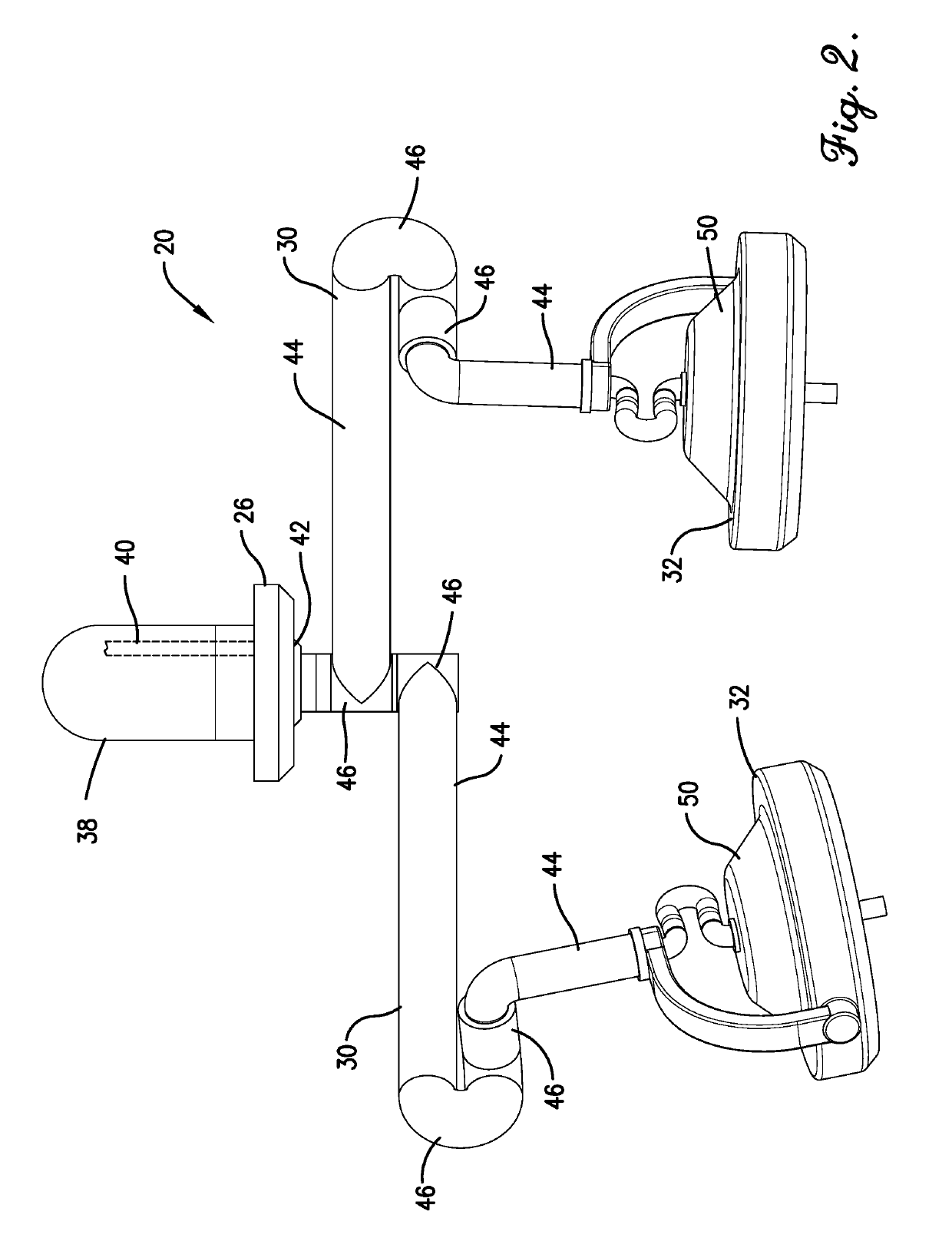
A system for providing laminar airflow over an operating platform having a top surface and a base. The system includes an airflow delivery apparatus and a return plenum. The airflow delivery apparatus is positioned above the top surface of the operating platform and includes a light assembly and a plurality of vents. The light assembly is configured to direct light toward the operating table. The plurality of vents is positioned around the light source and configured to direct airflow toward the top surface of the operating platform. The return plenum is positioned in the base of the operating platform below the top surface and is configured to receive airflow from around the operating platform in order to achieve laminar airflow around the operating platform.

Description

CROSS-REFERENCE TO RELATED APPLICATIONS[0001]The present non-provisional patent application claims priority to U.S. provisional patent application titled “LAMINAR FLOW STERILE AIR DELIVERY SYSTEM”, Ser. No. 62 / 623,196, filed Jan. 29, 2018, the entirety of which is hereby incorporated by reference into this non-provisional patent application.BACKGROUND[0002]Surgical suites, such as hospital emergency rooms (ERs) and operating rooms (ORs), are among the most infection-sensitive environments in healthcare facilities. Surgical procedures increase patient vulnerability to pathogens transmitted from surgical personnel, surgical equipment, contaminated air, and the patient's own skin flora.[0003]Despite advancements in surgical techniques and infection-prevention methods, surgical-site infections (SSIs) persist. As used herein, the term surgical “site” is used to mean the location on the patient where surgery is being performed (e.g., the surgical wound). Squames, or skin flakes or scales,...

Claims


Application Information

Patent Timeline
Patent Type & Authority Applications(United States)
IPC IPC(8): F24F13/078A61G13/10F24F7/06F24F7/003F24F8/108
CPCF24F13/078A61G13/108F24F7/06F24F2007/001F24F2221/10F24F2007/003F21W2131/205F24F3/044A61G12/004A61G12/005A61G12/008F24F3/163F24F8/108F24F7/003F24F2007/0025
Inventor HAAR, JONATHAN
Owner HAAR JONATHAN
Why Eureka
Try Eureka